
Hair drying device

Inactive Publication Date: 2014-05-29
HADDEN DAVID M
View PDF8 Cites 27 Cited by
  • Summary
  • Abstract
  • Description
  • Claims
  • Application Information

AI Technical Summary

Benefits of technology

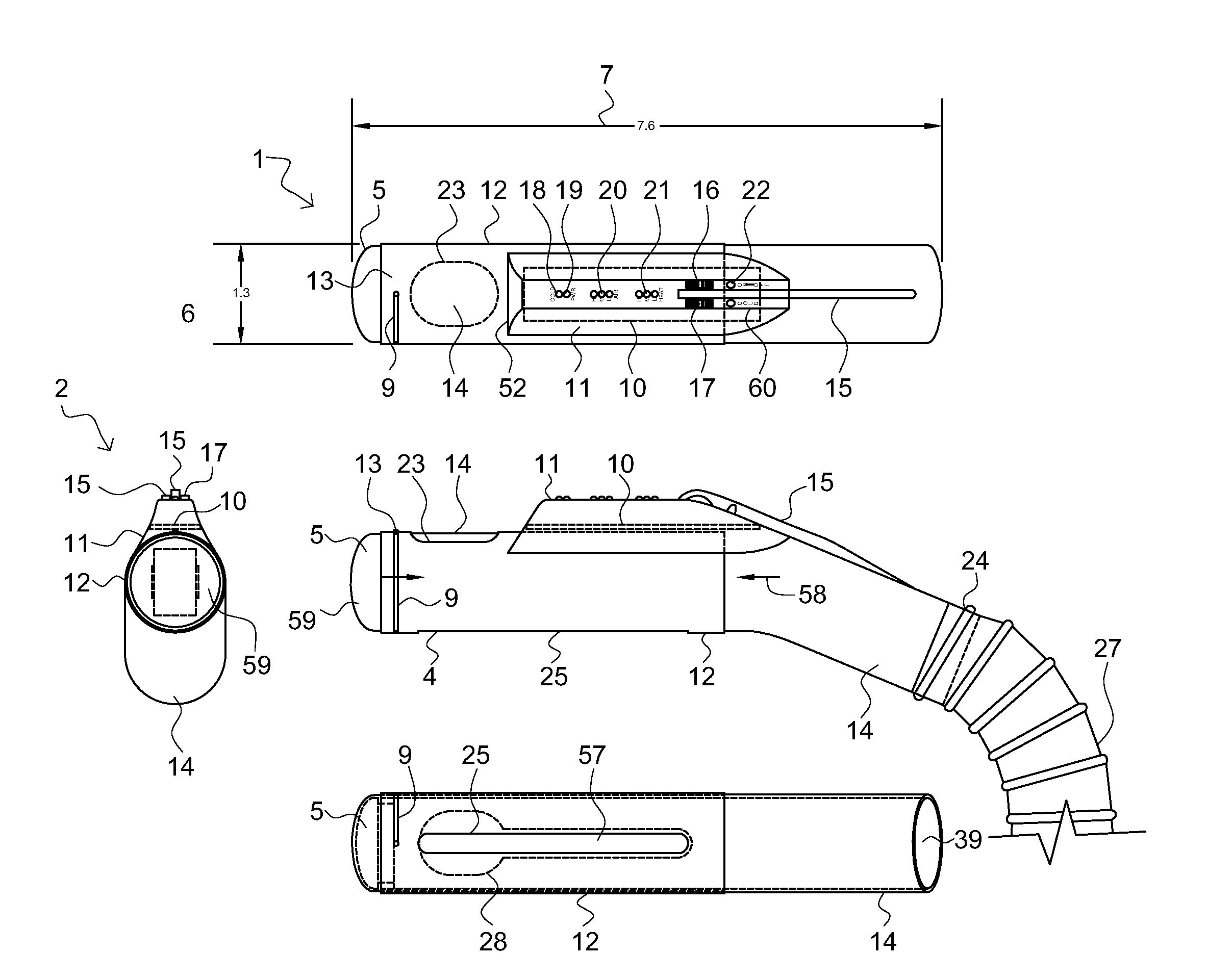
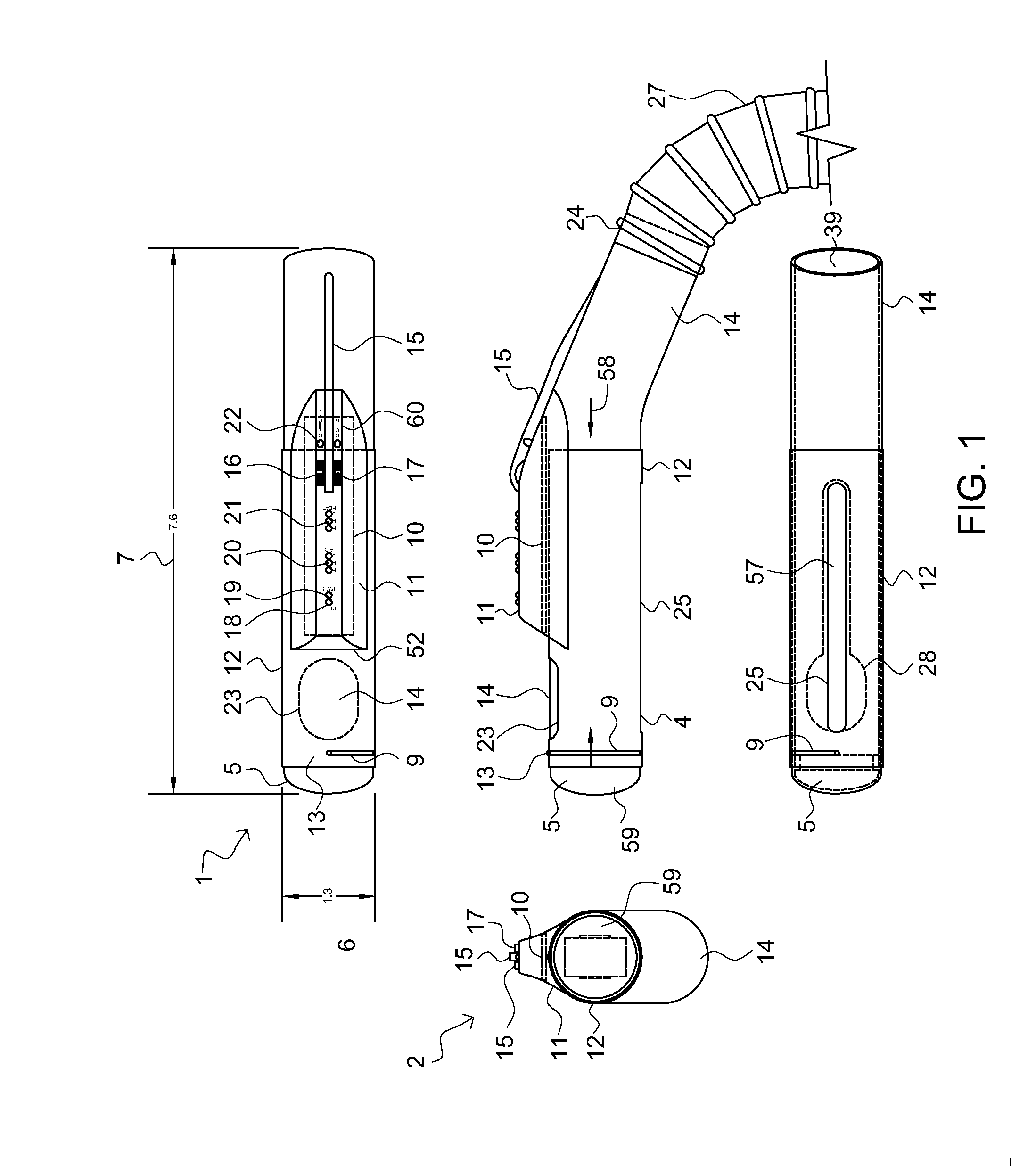
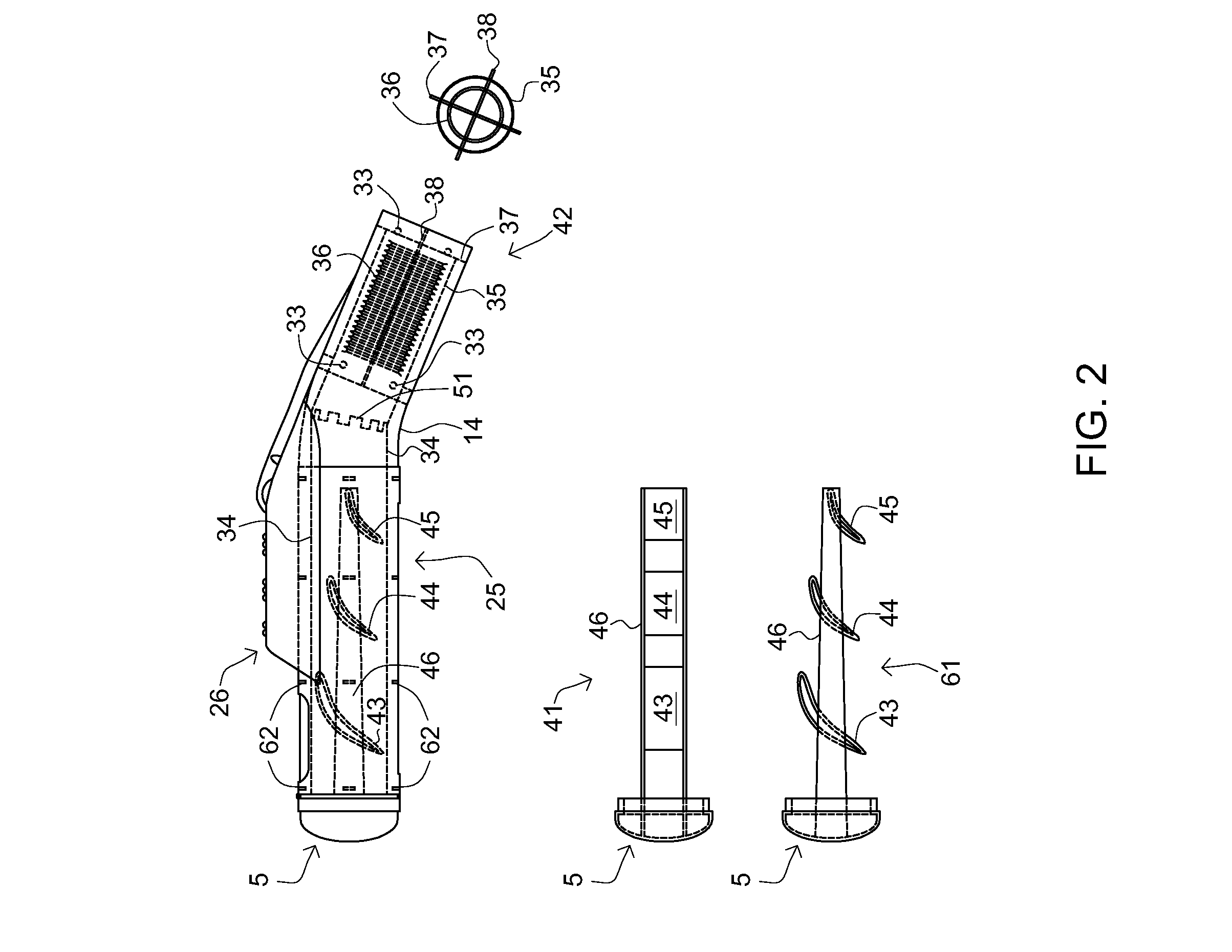
The present invention is a hair dryer that aims to solve the problems and needs of the current art. The invention includes a narrow elongated nozzle that generates airflow in the form of a thin blade of air, and a second nozzle that is oriented substantially orthogonal to the narrow elongated nozzle. The hair dryer may also include an airflow equalization structure that helps to evenly distribute airflow. The invention may also include a sleeve that is rotatably coupled about the nozzle and has a plurality of diversely shaped nozzle masks to restrict airflow in various modes. The invention may also include a vane structure that directs airflow to regions of the nozzle with reduced airflow. Overall, the invention provides a more effective and efficient solution for hair drying and styling.

Problems solved by technology

Only a small proportion of the molecules meet these criteria, so the rate of water evaporation is limited.
These result in reduced drying time and comfort during and after drying.
The inventions heretofore known suffer from a number of disadvantages which include being limited in use, being limited in application, being difficult to use, being unable to straighten hair, being limited in motion, being limited in adjustability, failing to provide optimal settings, being too heavy, being too noisy, causing harm to stylists through repeated use, failing to produce sufficient airflow, failing to sufficiently heat air, being inflexible, being awkward to use, producing noise at an undesired high frequency, being unable to condition air with additives, causing the body of the hair dryer to get too hot, being single use / purpose, not permitting precise adjustment of the shape and / or direction of the heated airstream, not permitting a velocity profile of the heated air stream to be precisely adjusted, having an air stream that is too hot, not having selectability in the direction out of the device where the heated air stream exits, not properly mixing air in the air stream, not having substantially uniform airflow, having too slow a response to heating and cooling setting changes, not having a balanced handle, being too likely to set off a circuit breaker, causing strain to stylists using the dryer, being noisy and having too many parts.

Method used


Image

  • Hair drying device
  • Hair drying device
  • Hair drying device

Examples


Embodiment Construction

[0038]For the purposes of promoting an understanding of the principles of the invention, reference will now be made to the exemplary embodiments illustrated in the drawing(s), and specific language will be used to describe the same. It will nevertheless be understood that no limitation of the scope of the invention is thereby intended. Any alterations and further modifications of the inventive features illustrated herein, and any additional applications of the principles of the invention as illustrated herein, which would occur to one skilled in the relevant art and having possession of this disclosure, are to be considered within the scope of the invention.

[0039]Many of the functional units described in this specification have been labeled as modules, in order to more particularly emphasize their implementation independence. For example, a module may be implemented as a hardware circuit comprising custom VLSI circuits or gate arrays, off-the-shelf semiconductors such as logic chips...


PUM


Abstract

A hair dryer including a blower and a dryer head having a narrow elongated nozzle shaped to generate airflow in the form of a thin blade of air. The hair dryer includes an airflow evening structure functionally coupled to the nozzle that more evenly distribute airflow of the thin blade of air. The airflow evening structure is a sleeve rotatably coupled about the nozzle and includes a plurality of diversely shaped nozzle masks disposed about the sleeve, each shaped to restrict airflow through the nozzle in varying modes.

Description

CROSS-REFERENCE TO RELATED APPLICATIONS[0001]This application is a Continuation-In-Part application of, under 35 U.S.C. §121, and claims priority to, under 35 U.S.C. §121, U.S. Non-Provisional application Ser. No. 13 / 687,989, entitled Hair Drying Device, by David M. Hadden, filed on Nov. 28, 2012. This invention claims priority, under 35 U.S.C. §120, to the U.S. Provisional Patent Application No. 61 / 564,241 by David M. Hadden filed on Nov. 28, 2011, which is incorporated by reference herein in its entirety.BACKGROUND OF THE INVENTION[0002]1. Field of the Invention[0003]The present invention relates to drying devices, specifically to a hair drying device.[0004]2. Description of the Related Art[0005]A blow dryer or hair dryer is an electromechanical device designed to blow cool or hot air over wet or damp hair, in order to accelerate the evaporation of water particles and dry the hair. Blow dryers allow to better control the shape and style of hair.[0006]For molecules of water to evap...

Claims


Application Information

Patent Timeline
IPC IPC(8): A45D20/00
CPCA45D20/00A45D20/16A45D20/122
Inventor HADDEN, DAVID M.
Owner HADDEN DAVID M
Learn More