
PCB tact switch
- Summary
- Abstract
- Description
- Claims
- Application Information
AI Technical Summary
Benefits of technology
Problems solved by technology
Method used
Image

Examples
Embodiment Construction
[0045]Hereinafter, preferred embodiments will be explained in detail referring to attached drawings.
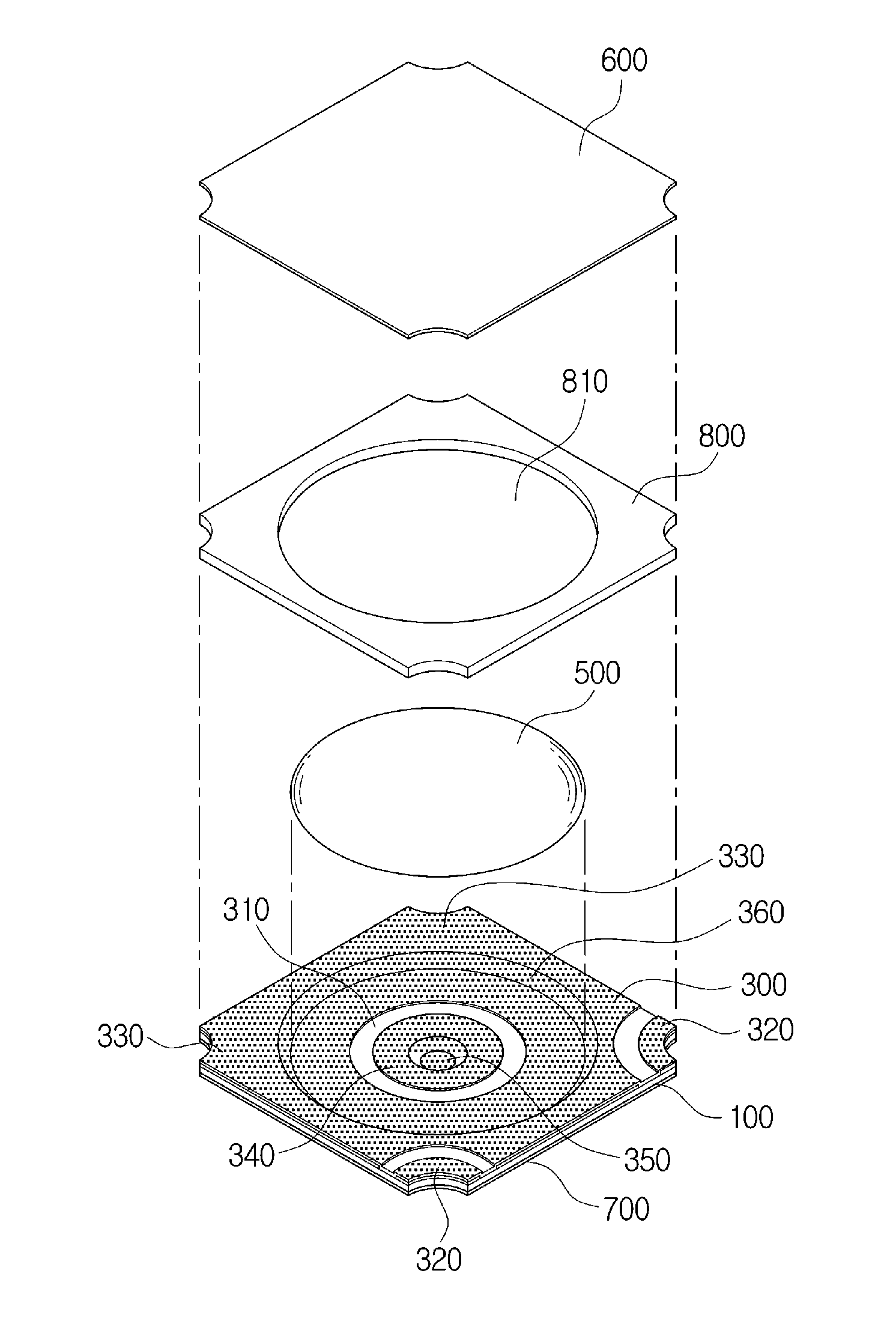
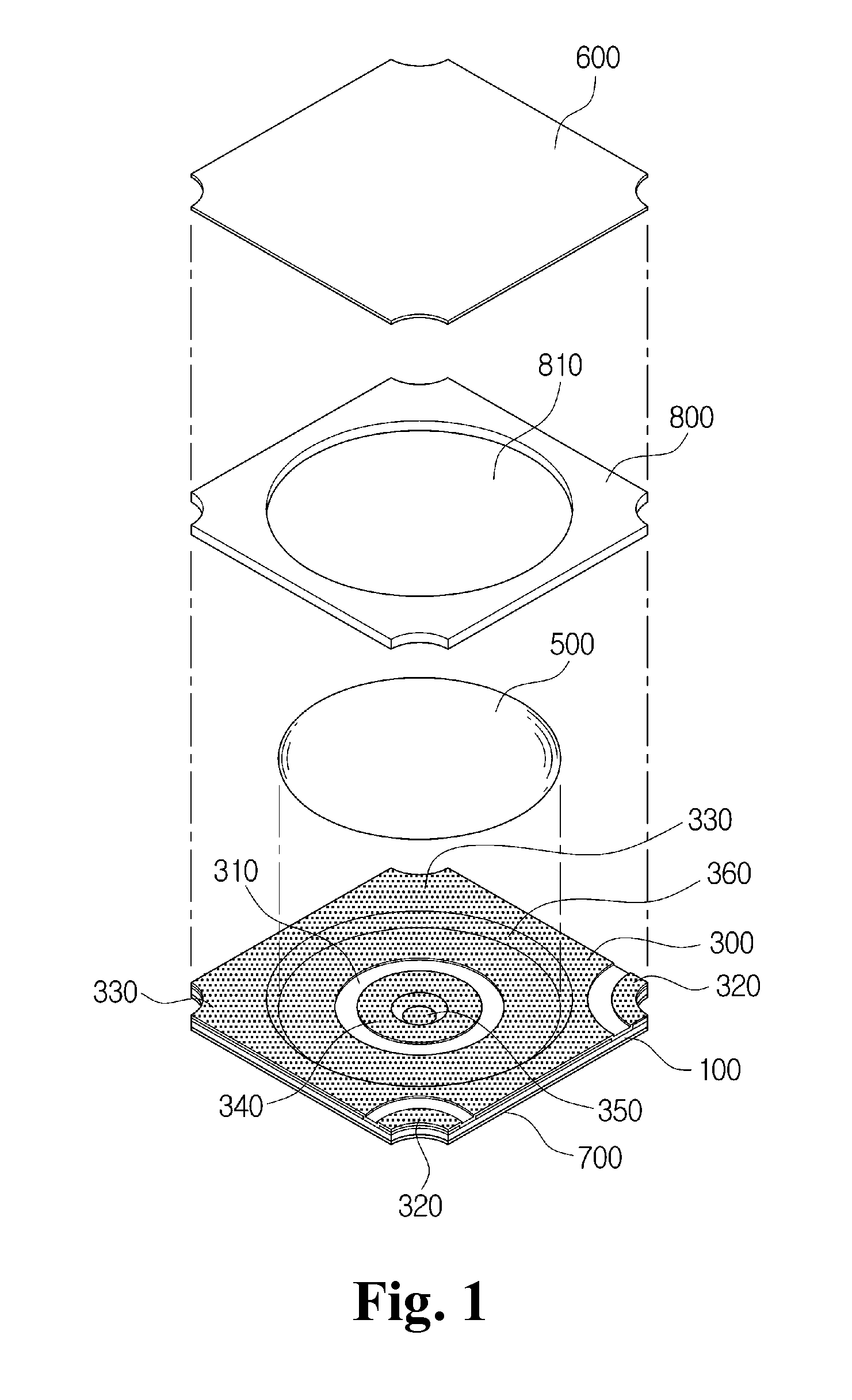
[0046]As shown in the figures, an insulation member 100 of a PCB-type tact switch according to the invention is in the form of a thin plate which is an electrical insulator has an upper surface on which an insulation film 111 is attached.
[0047]After the insulation film 111 adheres to the upper surface of the insulation member, a receiving hole 110 is made in the center of the insulator and the hole has a little larger diameter than an outer diameter of a metal dome 500.
[0048]An upper conductive substrate 300 is located above the insulation member 100.
[0049]As shown in FIG. 7, during the manufacturing a thin plate conductor, when a pressure is applied to the upper surface of the upper conductive substrate 300, the upper conductive substrate is deformed to fit into the receiving hole 110 of the insulation member 100 and is pressed to adhere to an insulation adhesive film 200 such that a...
PUM
 Abstract
Description
Claims
Application Information