
Normally Closed Magnetic Valve

Inactive Publication Date: 2014-05-29
ROBERT BOSCH GMBH
View PDF9 Cites 0 Cited by
  • Summary
  • Abstract
  • Description
  • Claims
  • Application Information

AI Technical Summary

Benefits of technology

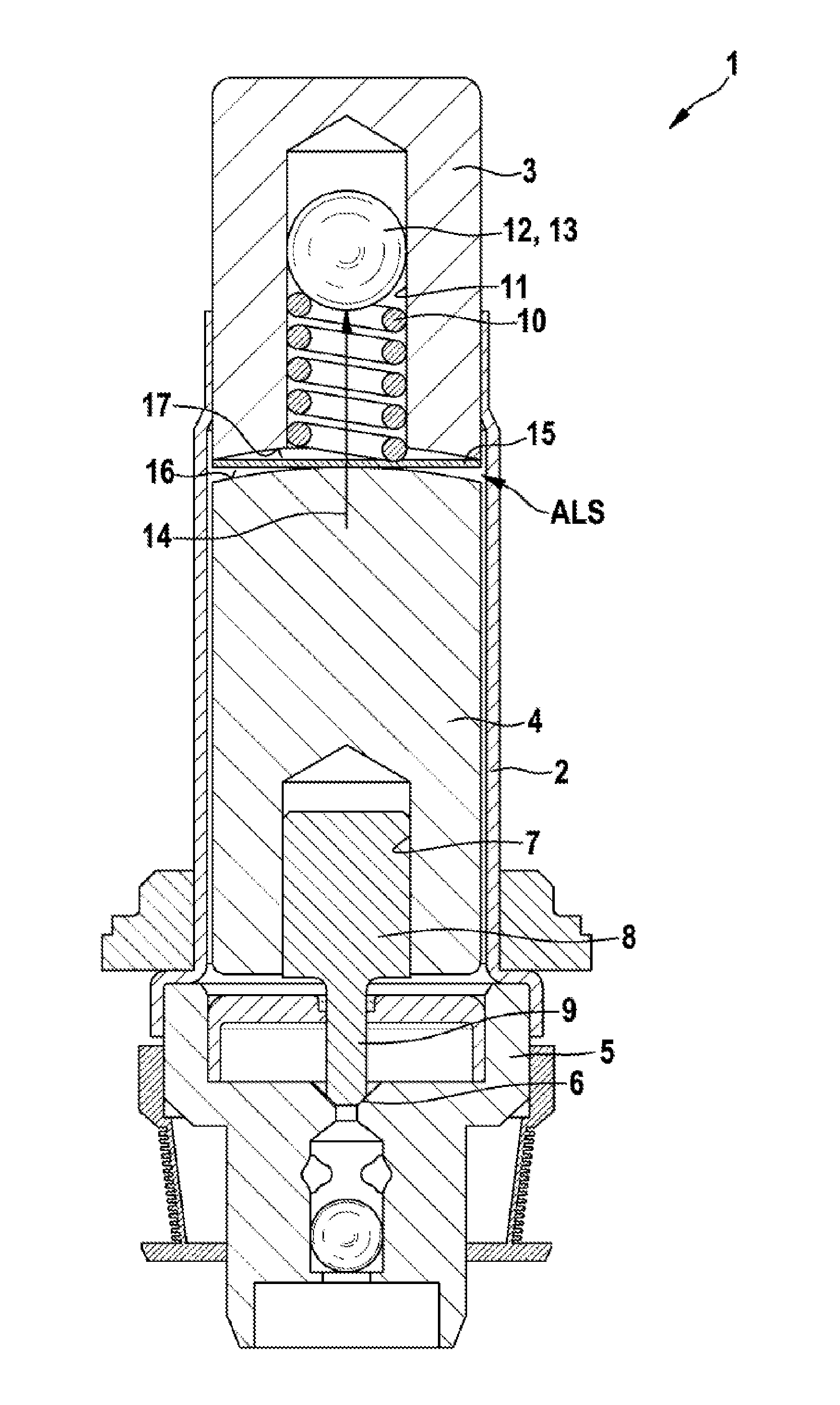
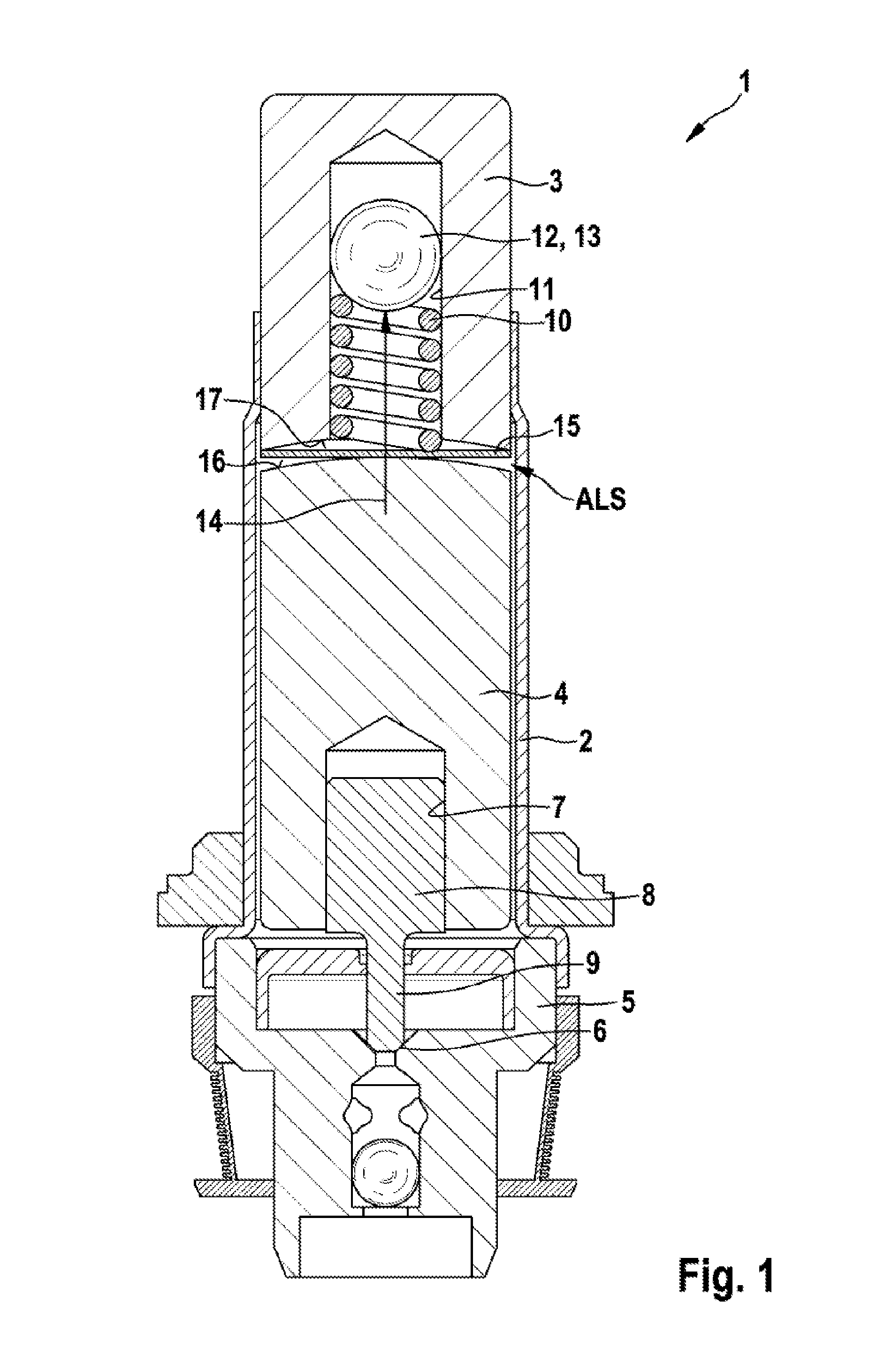
[0003]The magnetic valve according to the invention is characterized in that the pole core has an axial recess, in which the helical spring is received, at least in some regions. In contrast to the prior art, the helical spring is thus arranged in the pole core in this instance and is guided therethrough. In particular, this provides the advantage that the effective region of the arm

Problems solved by technology

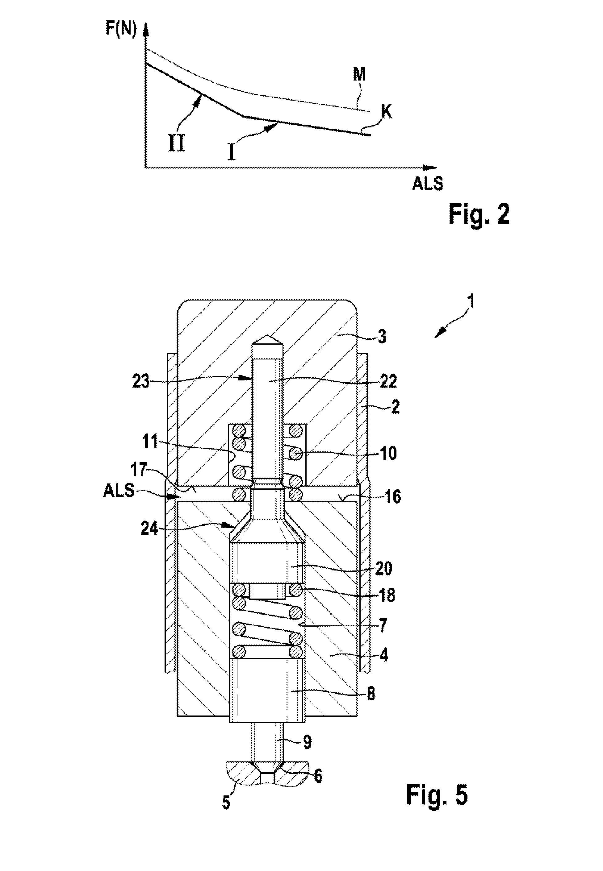
This increasing magnetic force profile hinders continuous adjustability (proportionalization) of the magnetic va

Method used


Image

  • Normally Closed Magnetic Valve
  • Normally Closed Magnetic Valve
  • Normally Closed Magnetic Valve

Examples


Example

[0019]FIG. 1 shows a simplified longitudinal sectional illustration of a magnetic valve 1, as is intended in particular for braking systems of motor vehicles, for example for ABS and / or ESP braking systems. The magnetic valve 1 has a valve sleeve 2, in which a pole core 3 of a magnetic actuator (not illustrated here in greater detail) is fixedly arranged. Furthermore, an armature 4 is axially displaceable in the valve sleeve 2. A valve body 5 is held on the end of the valve sleeve 2 opposite the pole core 3. The valve body 5 has a valve seat 6 surrounding a valve opening. At its end facing the valve body 5, the armature 4 has an axial recess 7, in which a press-in part 8 is held with a friction fit, wherein the press-in part 8 forms a valve tip 9, which cooperates tightly with the valve seat 6 in the de-energized state of the magnetic valve 1.

[0020]In this case a helical spring 10 is provided, which acts between the pole core 3 and the armature 4 so as to push the valve tip 9 into t...


PUM


Abstract

The disclosure relates to a normally closed magnetic valve, having a valve sleeve, in which a pole core is fixedly arranged and in which an armature having a valve tip is axially movable, wherein a helical spring acts between the pole core and the armature in order to push the valve tip into a valve seat. The pole core has an axial recess in which at least part of the helical spring is received in order to guide same.

Description

[0001]The invention relates to a normally closed magnetic valve with a valve sleeve, in which a pole core is fixedly arranged and in which an armature having a valve tip is axially displaceable, wherein a helical spring acts between the pole core and the armature so as to push the valve tip into a valve seat.PRIOR ART[0002]Magnetic valves of the above-mentioned type are known from the prior art. They comprise a magnetic actuator, which comprises a magnet coil, to which current can be supplied, as well as a pole core, and acts on an armature that is axially displaceable in the valve sleeve. The armature in this case has a valve tip, which is pushed against a valve seat in the de-energized state of the magnetic actuator. The armature is held in the valve sleeve in a biased manner for this purpose. A helical spring that acts, or is biased, between the pole core and the armature is normally provided to apply the bias. The helical spring is supported in this case at one end on the fixedl...

Claims


Application Information

Patent Timeline
IPC IPC(8): F16K31/06
CPCB60T8/363F16K31/0655B60T8/36F16K31/06
Inventor ALAZE, NORBERT
Owner ROBERT BOSCH GMBH
Learn More