Image forming apparatus
- Summary
- Abstract
- Description
- Claims
- Application Information
AI Technical Summary
Benefits of technology
Problems solved by technology
Method used
Image
Examples
first embodiment
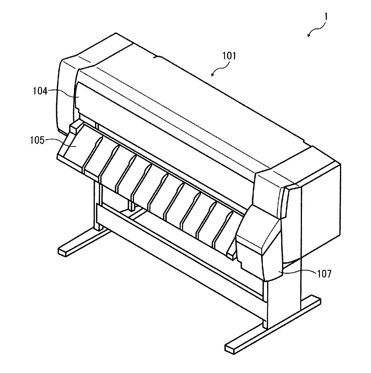
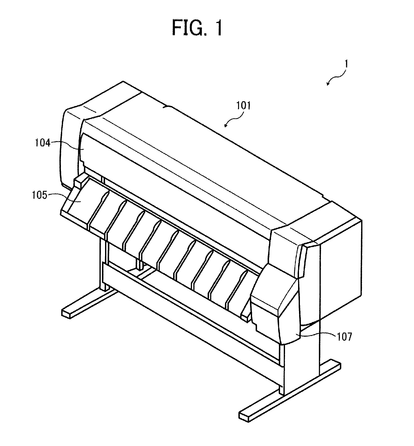
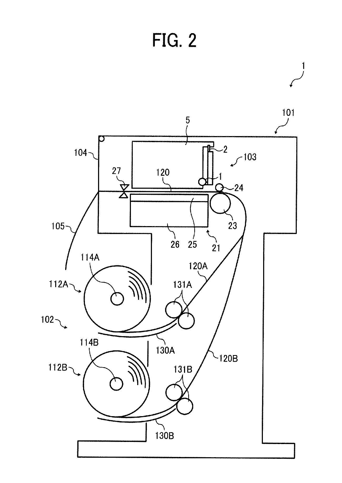
[0055]With reference to FIGS. 4 and 5, description will now be given of the access cover 104 and a guiding mechanism for guiding the access cover 104 according to the present invention. FIG. 4 is a partial perspective view of related parts of the access cover 104, as viewed from inside the apparatus body 101. FIG. 5 is a side view of a guide member provided to the apparatus body 101.
[0056]As illustrated in FIG. 4, the access cover 104 includes a lower first cover portion 104A and an upper second cover portion 104B, rotatably connected by a shaft 201 to be foldable. Further, each of opposed sides of the access cover 104 includes a hole 202, and projections 203 and 204, only one of each of which is shown in the view illustrated in FIG. 4. The hole 202 fits around a shaft (not illustrated) provided to the apparatus body 101. If a lower end portion of the access cover 104 is moved upward, therefore, the second cover portion 104B rotates about the hole 202, and the access cover 104 folds...
second embodiment
[0107]With reference to the schematic side view of FIG. 15, an access cover according to the present invention will now be described.
[0108]An access cover 404 according to the second embodiment is configured as a single cover having an upper portion rotatably held by a shaft 406. According to the second embodiment, a first detector 451 and a second detector 461 are provided. The first detector 451 turns off (or on) when the access cover 404 is opened from a fully closed position indicated by a solid line to a first position indicated by a dashed line. The second detector 461 turns off (or on) when the access cover 404 is opened to a second position indicated by a dash double-dotted line.
[0109]If the thus configured second embodiment has the configuration of the foregoing third example, for instance, it is possible to brake the main scanning motor 6 on the basis of a detection signal of the first detector 451 to stop the main scanning motor 6, and cut off the power feed path to the m...
PUM
 Abstract
Description
Claims
Application Information
 - R&D
- Intellectual Property
- Life Sciences
- Materials
- Tech Scout
- Unparalleled Data Quality
- Higher Quality Content
- 60% Fewer Hallucinations
Browse by: Latest US Patents, China's latest patents, Technical Efficacy Thesaurus, Application Domain, Technology Topic, Popular Technical Reports.
© 2025 PatSnap. All rights reserved.Legal|Privacy policy|Modern Slavery Act Transparency Statement|Sitemap|About US| Contact US: help@patsnap.com


