Dc/dc voltage converter and voltage conversion control method therefor

a voltage converter and voltage conversion technology, applied in the direction of dc-dc conversion, power conversion systems, instruments, etc., can solve the problems of dc/dc conversion, performance may deteriorate, transient voltage fluctuations, etc., and achieve the effect of suppressing transient voltage fluctuations (deterioration of dc/dc voltage conversion performance)

Active Publication Date: 2014-06-05
MITSUBISHI ELECTRIC CORP
View PDF0 Cites 11 Cited by
  • Summary
  • Abstract
  • Description
  • Claims
  • Application Information

AI Technical Summary

Benefits of technology

[0010]The present invention has been made to solve the problem described above, and it is an object thereof to provide a DC / DC voltage converter for suppressing transient voltage fluctuations (deterioration in DC / DC voltage conversion performance) caused by a discontinuous power loss of a power semiconductor unit as compared to the conventional DC / DC voltage converter.
[0012]According to the one embodiment of the present invention, it is possible to provide the DC / DC voltage converter for suppressing the transient voltage fluctuations (deterioration in DC / DC voltage conversion performance) caused by the discontinuous power loss of the power semiconductor unit as compared to the conventional DC / DC voltage converter.

Problems solved by technology

The above-mentioned conventional DC / DC voltage converter, however, has a problem in that the polarity of an inductor current IL may be only one of positive and negative or remain one of positive and negative depending on the change in load amount, which causes a discontinuous power loss of a power semiconductor unit of the DC / DC voltage converter, with the result that transient voltage fluctuations may occur in the DC / DC conversion and the performance may deteriorate.

Method used


Image

  • Dc/dc voltage converter and voltage conversion control method therefor
  • Dc/dc voltage converter and voltage conversion control method therefor
  • Dc/dc voltage converter and voltage conversion control method therefor

Examples


first embodiment

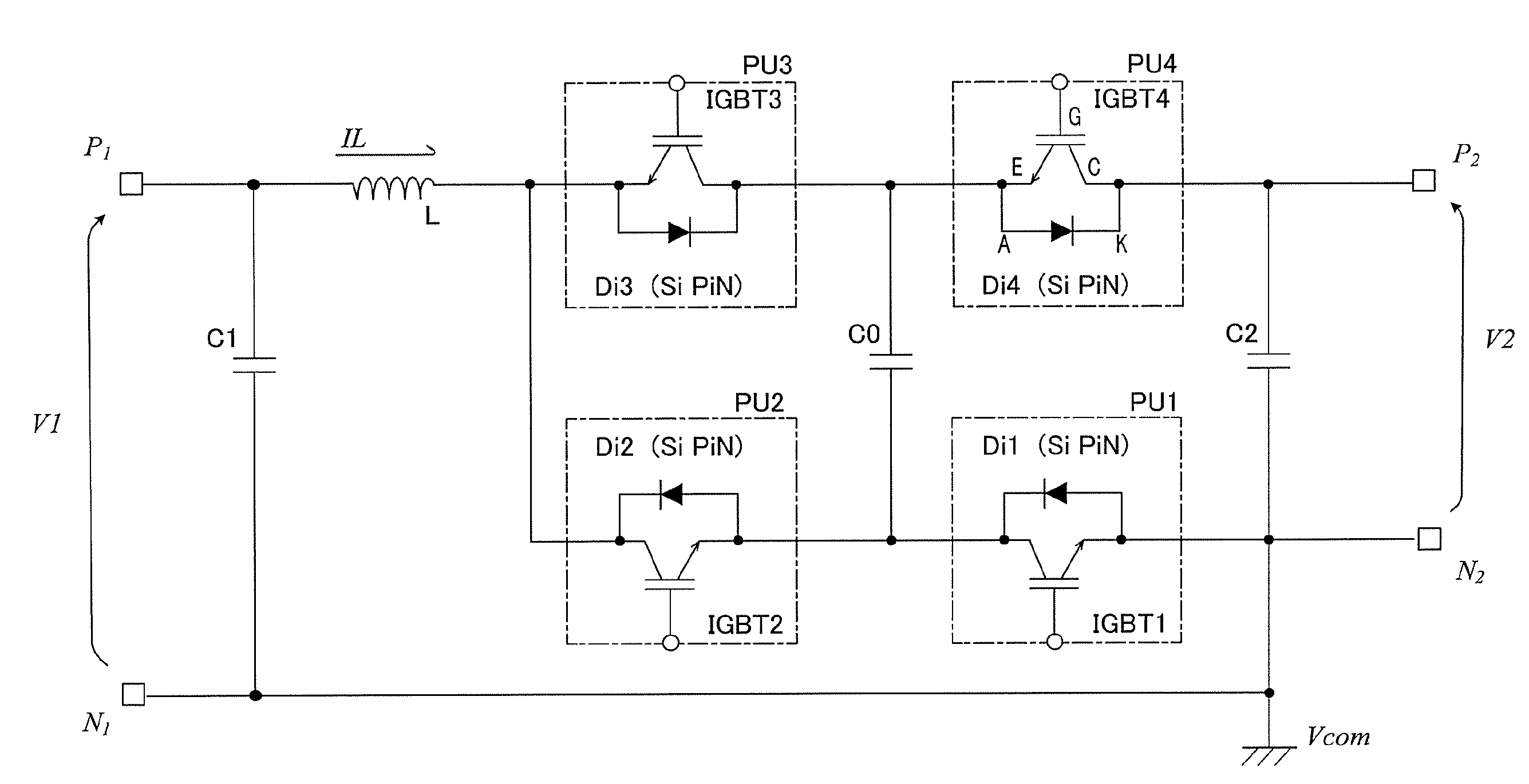
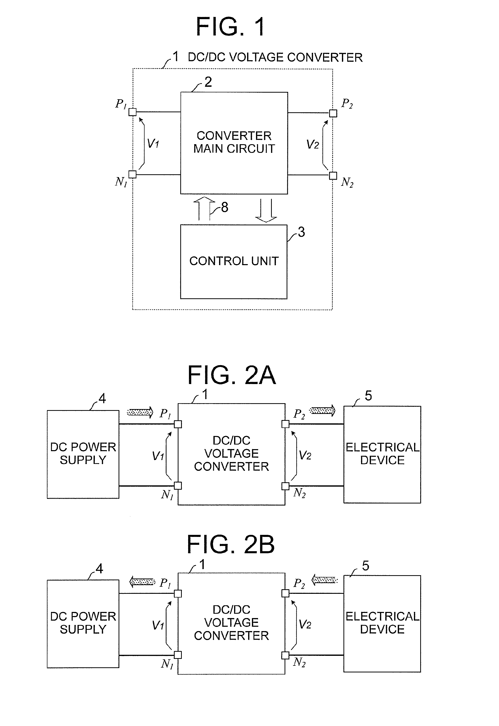
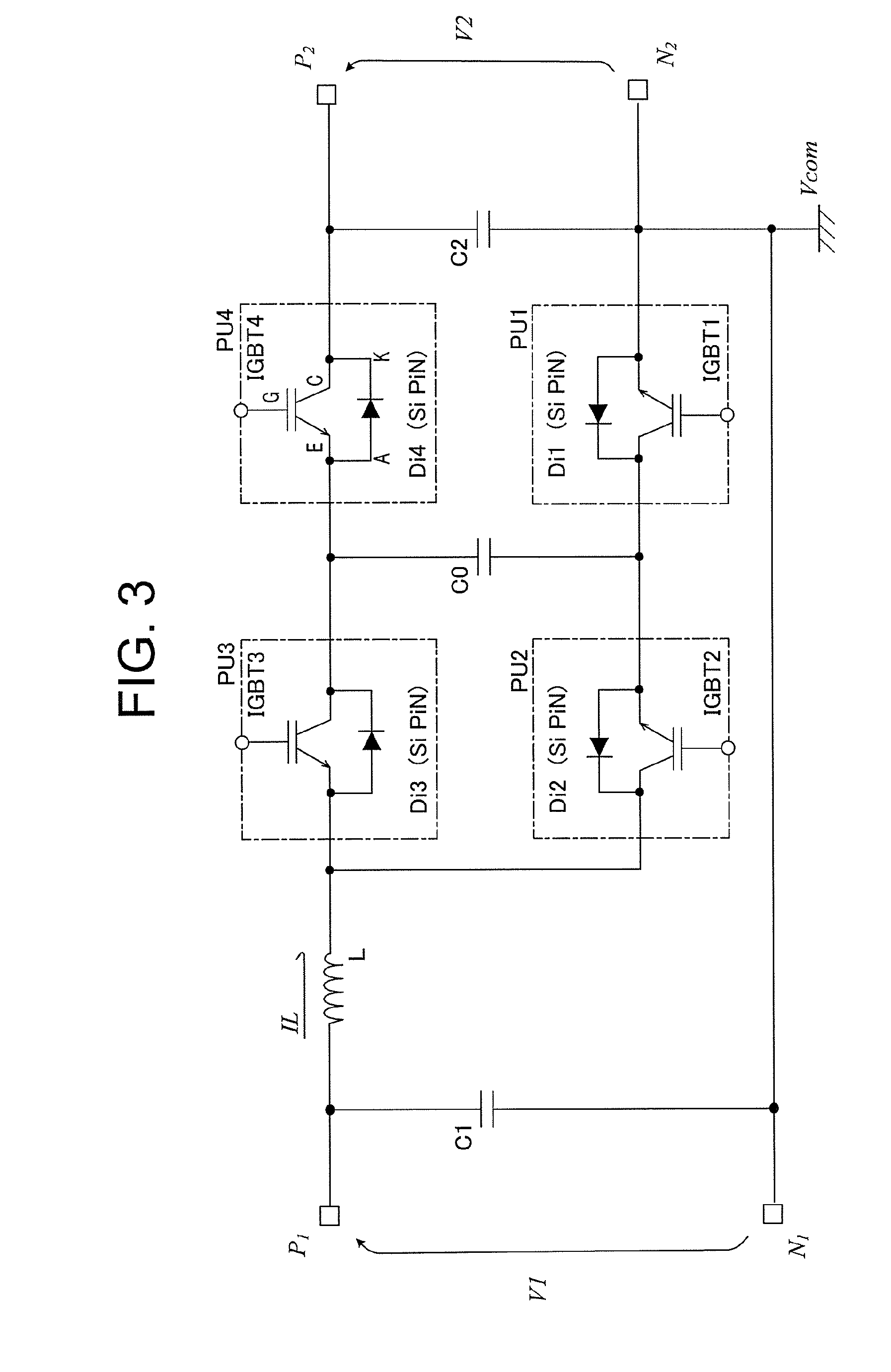
[0044]Referring to FIGS. 1 to 15, a DC / DC voltage converter according to a first embodiment of the present invention is now described. FIG. 1 is a block diagram illustrating an overall configuration of the DC / DC voltage converter according to the first embodiment of the present invention. A DC / DC voltage converter 1 includes a converter main circuit 2 and a control unit 3. The DC / DC voltage converter 1 includes, as connection terminals in a power path, a positive terminal P1 and a negative terminal N1 on the primary side of the converter main circuit 2 and a positive terminal P2 and a negative terminal N2 on the secondary side thereof (hereinafter sometimes abbreviated simply as “terminals”).

[0045]FIGS. 2A and 2B are diagrams schematically illustrating voltage conversion and the flow of electric power between the primary side and the secondary side of the DC / DC voltage converter according to the first embodiment. A DC power supply 4 is connected to the terminals P1 and N1 on the pri...

second embodiment

[0278]Referring to FIGS. 16 and 17, a DC / DC voltage converter according to a second embodiment of the present invention is now described.

[0279]The DC / DC voltage converter according to the second embodiment of the present invention has the same configuration, operation, and function as those of the DC / DC voltage converter according to the above-mentioned first embodiment, except for the operation of the gate PWM generating section 11 of the control unit 3. Descriptions of the same configuration, operation, and function as those in the first embodiment are hereinafter omitted as appropriate.

[0280]First, FIG. 16 is an explanatory diagram schematically showing the relationship between the inductor current IL and the switching of the switching frequency according to the second embodiment of the present invention.

[0281]In FIG. 16, the switching frequency is switched with a hysteresis of a width ΔILha with respect to the inductor current IL.

[0282]Specifically, when the absolute value of th...

third embodiment

[0295]Referring to FIGS. 18 to 20, a DC / DC voltage converter according to a third embodiment of the present invention is now described.

[0296]In the DC / DC voltage converter according to the third embodiment of the present invention, instead of using a bipolar PiN diode made of Si, a unipolar (unipolar semiconductor) Schottky barrier diode (SBD) made of silicon carbide (SiC) having a larger bandgap is used as diodes Di4a and Di3a as the rectifier elements of the converter main circuit 2.

[0297]The DC / DC voltage converter according to the third embodiment of the present invention has the same configuration, operation, and function as those of the DC / DC voltage converter according to the above-mentioned first embodiment, except for the configuration and operation of the converter main circuit 2. Descriptions of the same configuration, operation, and function as those in the first embodiment are hereinafter omitted as appropriate.

[0298]Reference is first made to FIG. 18. FIG. 18 illustrat...


PUM


Abstract

A power module includes at least two pairs of two power semiconductor units (PSUs), each of which includes a switch element and a rectifier element connected in anti-parallel. One of two PSUs in one pair and one of two PSUs in another pair are connected in series between primary and secondary positive terminals of a DC / DC voltage converter. Another of two PSUs in the one pair and another of two PSUs in the another pair are connected in series between the primary positive terminal and a secondary negative terminal in a direction reverse to a direction of the ones of two PSUs. Control is performed to suppress transient voltage fluctuations that occur in switching between the state where the polarity of a reactor current is only one of positive and negative and the state where the polarity remains one of positive and negative.

Description

BACKGROUND OF THE INVENTION[0001]1. Field of the Invention[0002]The present invention relates to a DC / DC voltage converter for converting a DC voltage into a stepped-up or stepped-down DC voltage, and a voltage conversion control method for a DC / DC voltage converter.[0003]2. Description of the Related Art[0004]A device for performing DC / DC voltage conversion has hitherto been used, which utilizes a switch-ON and switch-OFF operation of switch elements connected in series to perform a combination, of an operation of storing and discharging energy to and from an inductor and an operation of charging and discharging an energy transfer capacitor (see, for example, Japanese Patent Application Laid-open No. Hei 11-186478, and Mitsubishi Denki Giho, Vol. 61, No. 2, 1987).[0005]This DC / DC voltage converter has a circuit configuration in which at least four power devices, each including a switch element and a rectifier element connected in anti-parallel thereto, are connected in series. Only...

Claims


Application Information

Patent Timeline
Patent Type & Authority Applications(United States)
IPC IPC(8): H02M3/158
CPCH02M3/158H02M7/4837
Inventor KOBAYASHI, MASARUIKEDA, MATAHIKOMAEKAWA, HIROTOSHI
Owner MITSUBISHI ELECTRIC CORP
Why Eureka
Try Eureka