
Head-float and method

a head-float and head-float technology, applied in the field of methods and systems, can solve the problems of affecting the work efficiency of maintenance personnel, affecting the seismic survey, and affecting the accuracy of the seismic survey

Inactive Publication Date: 2014-06-05
CGG SERVICES SA
View PDF6 Cites 24 Cited by
  • Summary
  • Abstract
  • Description
  • Claims
  • Application Information

AI Technical Summary

Benefits of technology

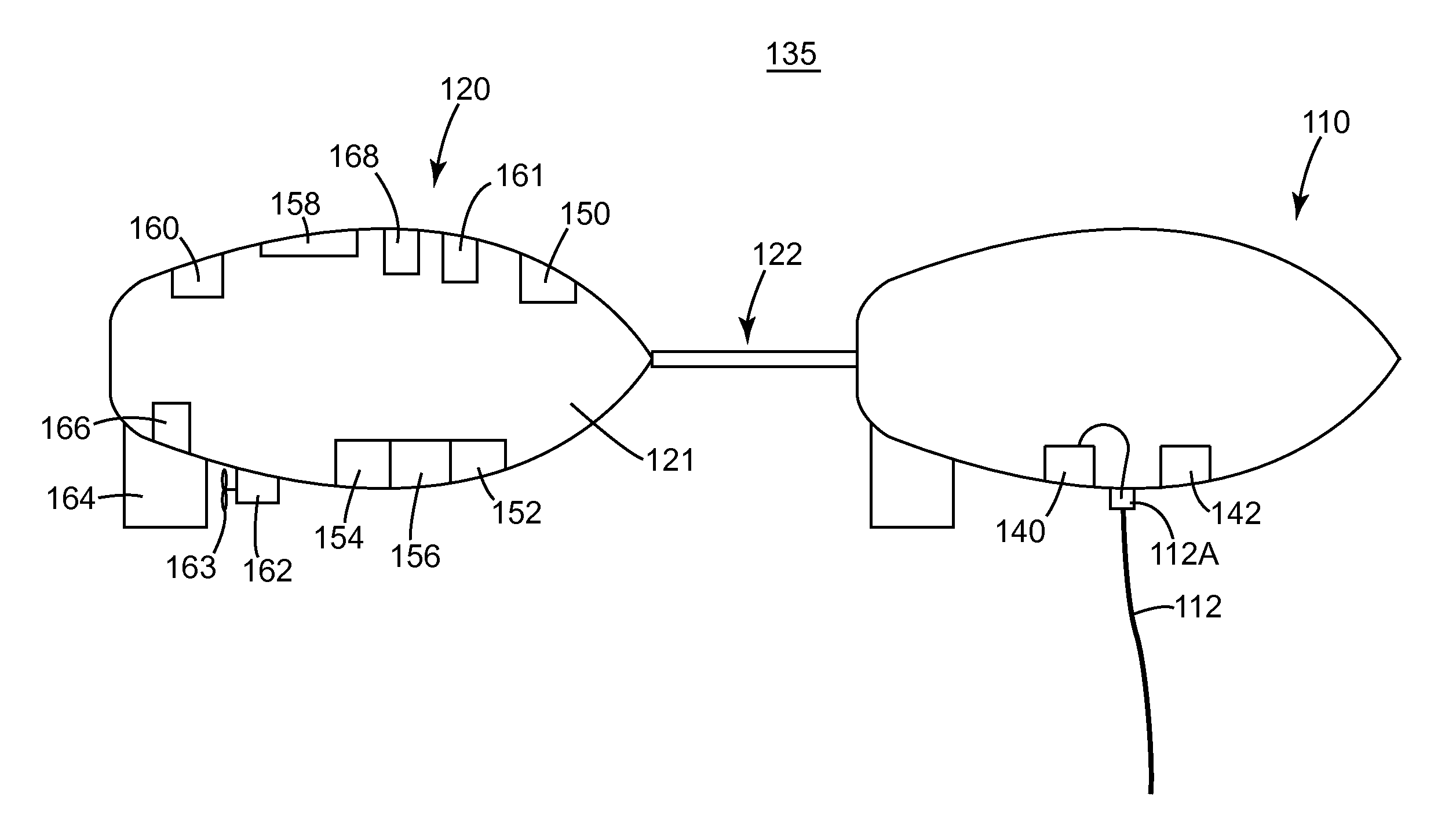
The patent describes a system for positioning equipment on a streamer in underwater seismic surveys. The system includes a head-buoy that floats in water and is connected to the streamer or lead-in, a head-float that also floats in water, a connector that connects the head-float to the head-buoy, and positioning equipment on the head-float that can determine the position of the streamer or the source. This system helps to accurately position the streamer and improve the quality of the seismic data.

Problems solved by technology

While this profile does not provide an accurate location for oil and gas reservoirs, it suggests, to those trained in the field, the presence or absence of them.
Such environment makes the working conditions difficult for the maintenance personnel due to, e.g., large waves, moving equipment, humid environment, etc.
Also, the maintenance may be time-consuming because the environmental conditions are not appropriate.
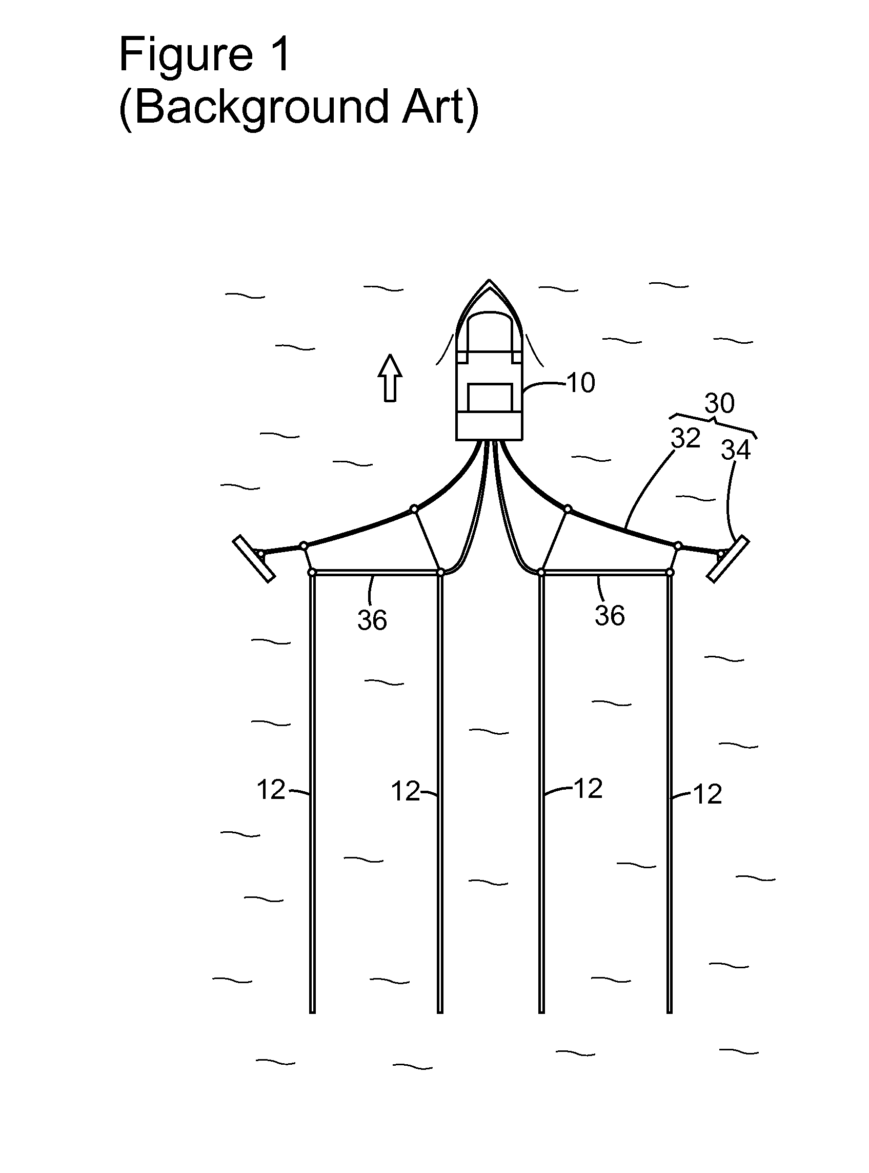
Having the streamer spread deployed underwater and the seismic survey stopped for head-buoy maintenance is highly undesirable because the cost of the streamer spread is high.
The head-float does not provide floatation to the streamer.

Method used


Image

  • Head-float and method
  • Head-float and method
  • Head-float and method

Examples


Embodiment Construction

[0032]The following description of the exemplary embodiments refers to the accompanying drawings. The same reference numbers in different drawings identify the same or similar elements. The following detailed description does not limit the invention. Instead, the scope of the invention is defined by the appended claims. The following embodiments are discussed, for simplicity, with regard to the terminology and structure of a head-float that is connected to a head-buoy.

[0033]Reference throughout the specification to “one embodiment” or “an embodiment” means that a particular feature, structure or characteristic described in connection with an embodiment is included in at least one embodiment of the subject matter disclosed. Thus, the appearance of the phrases “in one embodiment” or “in an embodiment” in various places throughout the specification is not necessarily referring to the same embodiment. Further, the particular features, structures or characteristics may be combined in any...


PUM


Abstract

Method and streamer / source head-float system for connecting to a head portion of a streamer or to a lead-in or providing information about a source. The system includes a head-buoy configured to float in water and connected through a cable to the head portion of the streamer or to the lead-in; a head-float configured to float in water; a connector connecting the head-float to the head-buoy; and positioning equipment attached to the head-float and configured to determine a position of the streamer or the source.

Description

BACKGROUND[0001]1. Technical Field[0002]Embodiments of the subject matter disclosed herein generally relate to methods and systems and, more particularly, to mechanisms and techniques for improving and making more efficient a maintenance task associated with a head-buoy.[0003]2. Discussion of the Background[0004]Seismic data acquisition and processing generate a profile (image) of geophysical structures under seafloor or subsoil. While this profile does not provide an accurate location for oil and gas reservoirs, it suggests, to those trained in the field, the presence or absence of them. Thus, providing a high-resolution image of the structures under the seafloor / subsoil is an ongoing process.[0005]To construct images of the subsoil (or subsurface), geologists or geophysicists conventionally use, for example, wave emitters (sources) placed on the surface. For the case of marine seismic surveys, the wave emitters are towed by a vessel at or under the surface of the water. Such emitt...

Claims


Application Information

Patent Timeline
IPC IPC(8): G01V1/38
CPCB63B21/66B63B22/04G01V1/3843G01V1/3835G01V1/38
Inventor TONCHIA, HELENE
Owner CGG SERVICES SA
Learn More