Eureka AIR delivers breakthrough ideas for toughest innovation challenges, trusted by R&D personnel around the world.

Fiber optic observatory link for medium bandwidth data communication

a fiber optic observatory and data communication technology, applied in electromagnetic transmission, electrical equipment, electromagnetic network arrangements, etc., can solve the problems of large, cumbersome and costly deployment, severe limitations in the distance that instruments can be deployed from the observatory, etc., and achieve low cost, low power, and easy deployment

Inactive Publication Date: 2011-03-10
WOODS HOLE OCEANOGRAHIC INSTION
View PDF9 Cites 52 Cited by
  • Summary
  • Abstract
  • Description
  • Claims
  • Application Information

AI Technical Summary

Benefits of technology

The systems and methods described herein provide a reconfigurable, long-range, underwater data-communication network. In particular, the network provides a low cost, low power, lightweight, and easy to deploy underwater communication system capable of being operated at long distances.
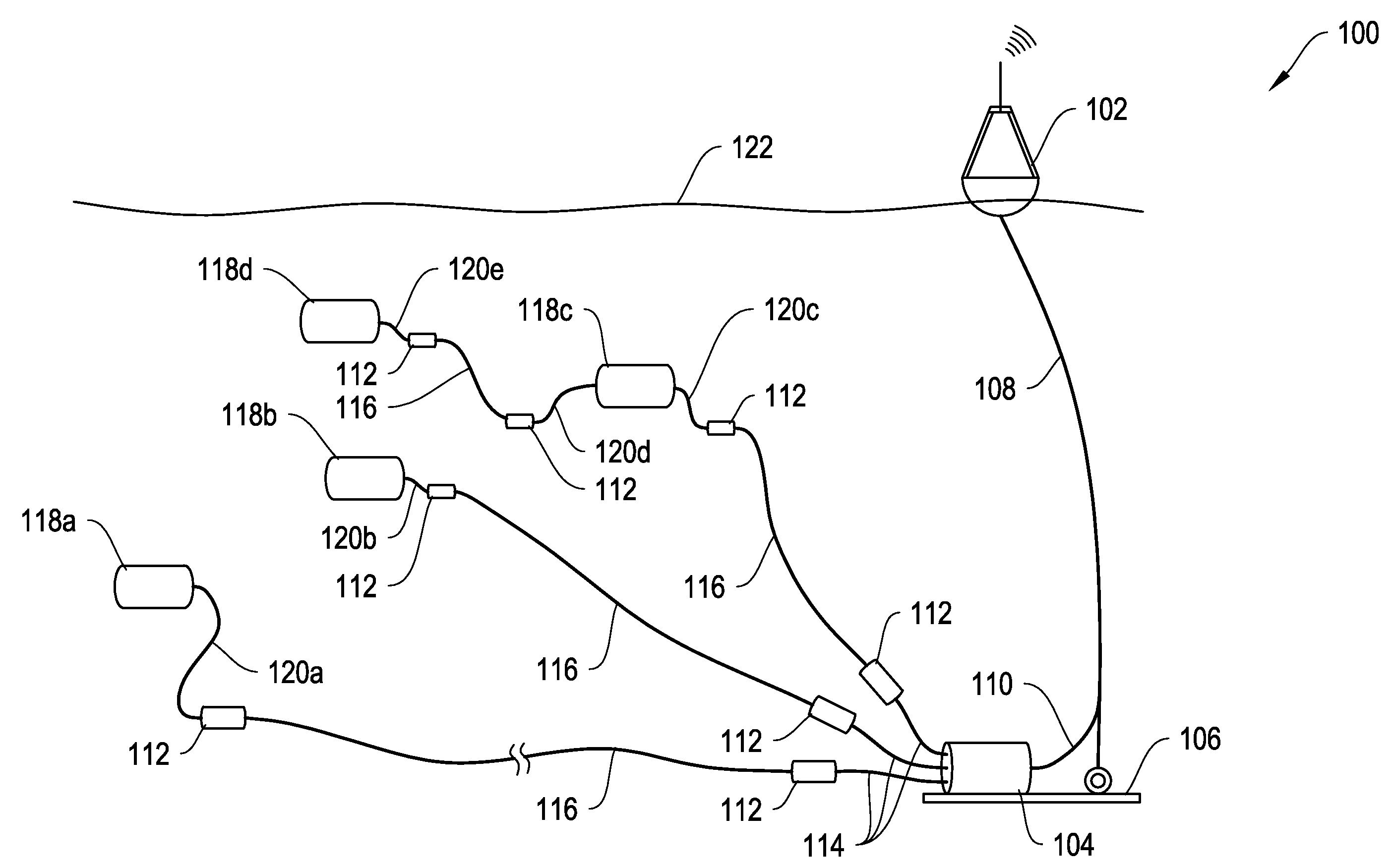
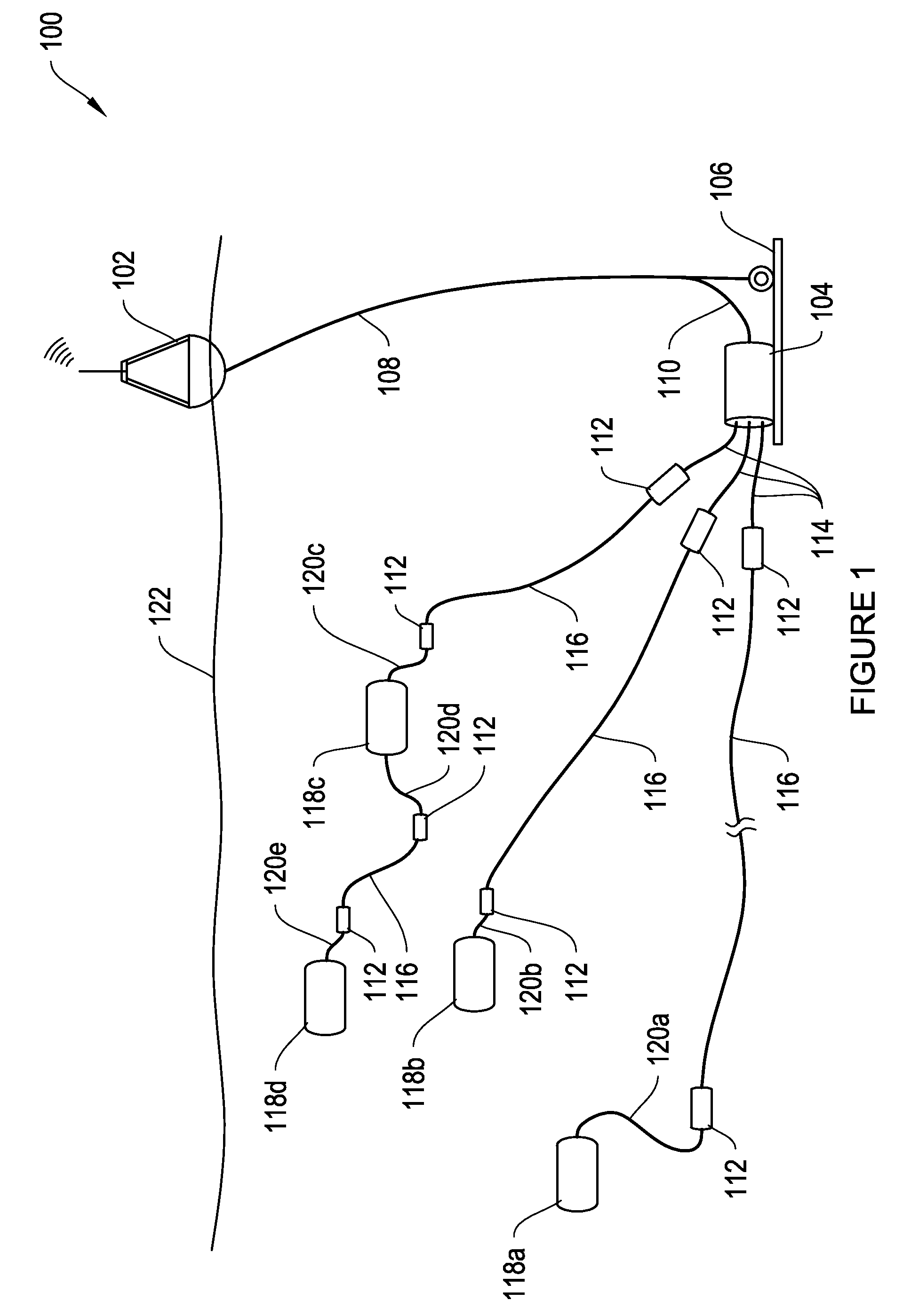
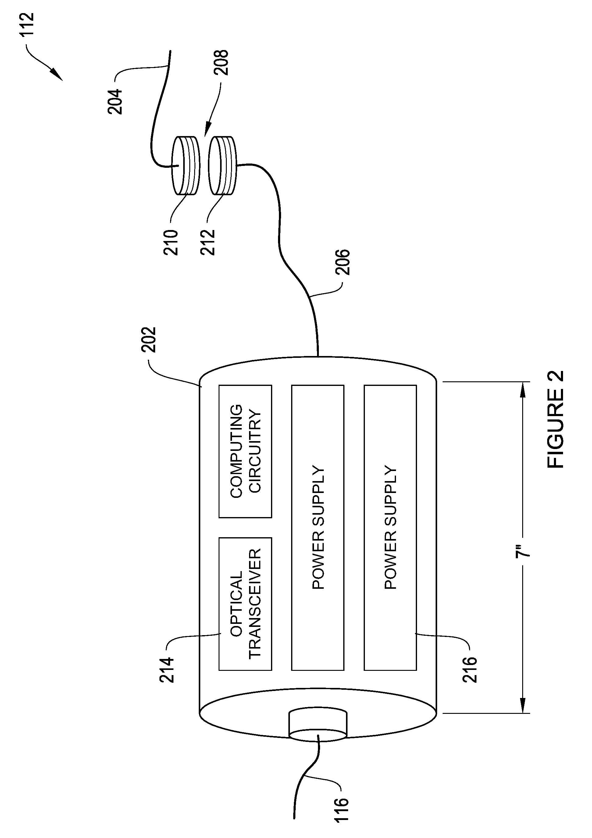
In one aspect, a reconfigurable, long-range, underwater data-communication network may include a cabled ocean observatory, which may be deployed underwater and connected to a surface buoy. The cabled ocean observatory may be connected to one or more removable underwater sensors via fiber optic cables. The underwater sensors may be disposed at underwater locations at long distances from the cabled ocean observatory. Fiber optic extension modules may be permanently connected to each end of the fiber optic cables. Each fiber optic extension module may include an optical transceiver, a power supply, and an inductive element for removably coupling an underwater sensor or the cabled ocean observatory to the fiber optic cable.
In some embodiments, the optical transceiver of the fiber optic extension module may include a laser configured to operate such that the module has a total power consumption of less than about 1 W when transmitting data at distances of over 100 km at about 9600 baud. In some embodiments, the laser may be configured to transmit data using an on-off keying protocol. In some embodiments, the optical transceiver may minimize power consumption by operating only when a detector receives optical signals. In some embodiments, the fiber optic extension module may be enclosed in a waterproof housing. In some embodiments, the fiber optic extension module may include one or more LiH batteries as power supplies. In some embodiments, the fiber optic extension module may weigh less than about 20 kg. In some embodiments, the fiber optic extension modules may be arranged in a mesh architecture, a bus architecture, a ring architecture, or a star architecture.

Problems solved by technology

Although existing and proposed observatory systems promise high electrical power and real-time communications, they have severe limitations with regard to the distance that instrumentation can be deployed from the observatory (either coastal, regional, or buoys) due to power, communications, and cost constraints.
In addition these devices are large, heavy, and deployment is cumbersome and costly, often requiring an ROV.

Method used


Image

  • Fiber optic observatory link for medium bandwidth data communication
  • Fiber optic observatory link for medium bandwidth data communication
  • Fiber optic observatory link for medium bandwidth data communication

Examples


Embodiment Construction

The systems and methods described herein will now be described with reference to certain illustrative embodiments. However, the invention is not to be limited to these illustrated embodiments which are provided merely for the purpose of describing the systems and methods of the invention and are not to be understood as limiting in anyway.

FIG. 1 depicts a long range subsea sensor and communication network 100, according to an illustrative embodiment of the invention. System 100 includes a cabled ocean observatory 104 submerged under a water body 122 at a desired depth. A cabled ocean observatory may be designed around either a surface buoy containing an autonomous power source and wireless (e.g., satellite) communications link or a submarine fiber optic / power cable connecting one or more seafloor science nodes to the terrestrial power grid and communications backhaul. A cabled ocean observatory may provide unprecedented amounts of power and two-way bandwidth to access and control ins...


PUM


Abstract

Systems and methods for a reconfigurable, long-range, underwater data-communication network are described. The network provides a low cost, low power, lightweight, and easy to deploy underwater communication system capable of being operated at long distances. The network may include a cabled ocean observatory, which may be deployed underwater and connected to a surface buoy. The cabled ocean observatory may be connected to one or more removable underwater sensors via fiber optic cables. The underwater sensors may be disposed at underwater locations at long distances from the cabled ocean observatory. Fiber optic extension modules may be permanently connected to each end of the fiber optic cables. Each fiber optic extension module may include an optical transceiver, a power supply, and an inductive element for removably coupling an underwater sensor or the cabled ocean observatory to the fiber optic cable.

Description

BACKGROUND OF THE INVENTIONThere is an increasing need for long term observation of large portions of the earth-ocean system. In particular, scientists wish to monitor oceanic processes as well as improve predictive modeling of complex natural phenomena that vary over distance and time. Ocean observatories are being deployed at the seafloor and connected by cable or buoy to surface networks to help scientists study these oceanic processes. These observatories are really large computer and power networks having scientific equipment such as spectrometers or seismometers. These seafloor observatories may be located many hundreds of kilometers off the coast of the nearest shore station and may be positioned at depths of over 5000 meters. Typically, the observatory has one or more network connections to shore stations through which data collected from the seafloor observatory can be passed onto the Internet and which can serve seafloor instruments with power and control commands. Althoug...

Claims


Application Information

Patent Timeline
IPC IPC(8): H04B13/02
CPCH04B10/272
Inventor CAMILLI, RICHARDSONNICHSEN, FREDERICKBRADLEY, ALBERT M.LERNER, STEVEN A.
Owner WOODS HOLE OCEANOGRAHIC INSTION
Why Eureka
Eureka Blog
Learn More