Eureka AIR delivers breakthrough ideas for toughest innovation challenges, trusted by R&D personnel around the world.

Solid state power source with frames for attachment to an electronic circuit

Active Publication Date: 2014-06-05
MEDTRONIC INC +1
View PDF1 Cites 4 Cited by
  • Summary
  • Abstract
  • Description
  • Claims
  • Application Information

AI Technical Summary

Benefits of technology

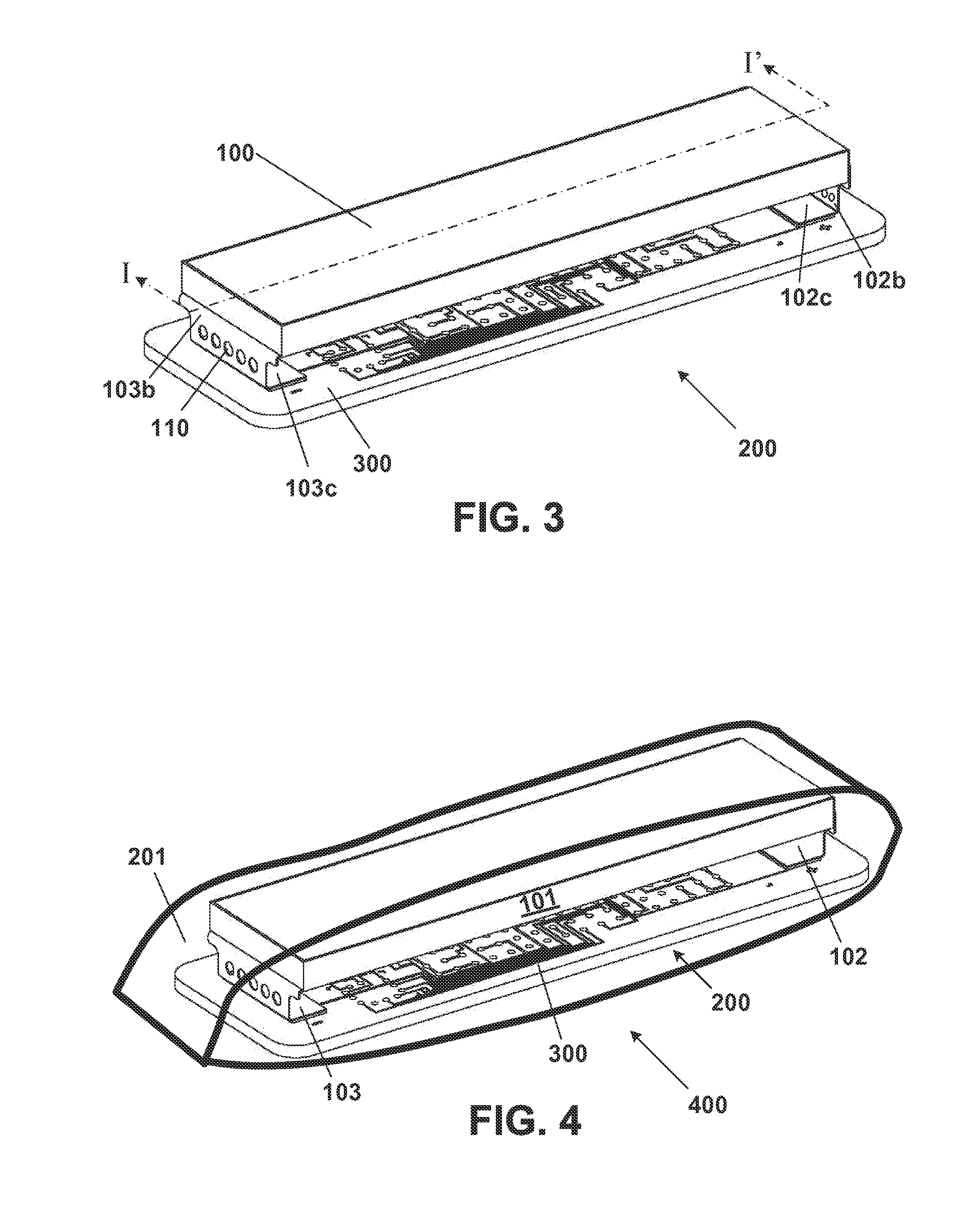
The invention provides a way to attach an electrochemical cell directly to the electronic circuitry of an implantable device. This attachment is achieved through a mechanical and electrical connection, which ensures a secure and tight seal between the two components. The invention also involves attaching the electrochemical cell to frames using the attachment architecture, ensuring that the terminals are connected both mechanically and electrically to the electronic circuitry. This allows for a more efficient and secure attachment of the electrochemical cell to the device.

Problems solved by technology

However, such a battery holder with the button or coin cell fixated into a metal spring clip in turn consumes premium volume / space.
However, the use of premium volume / space on spring clips as well as other auxiliary battery holder / encasement materials can be unacceptable, up to the point where an implantable enclosure with a specific type of electronic circuitry may not make sense with regard to particular applications (e.g. medical), such as those with severe space or size limitations.

Method used


Image

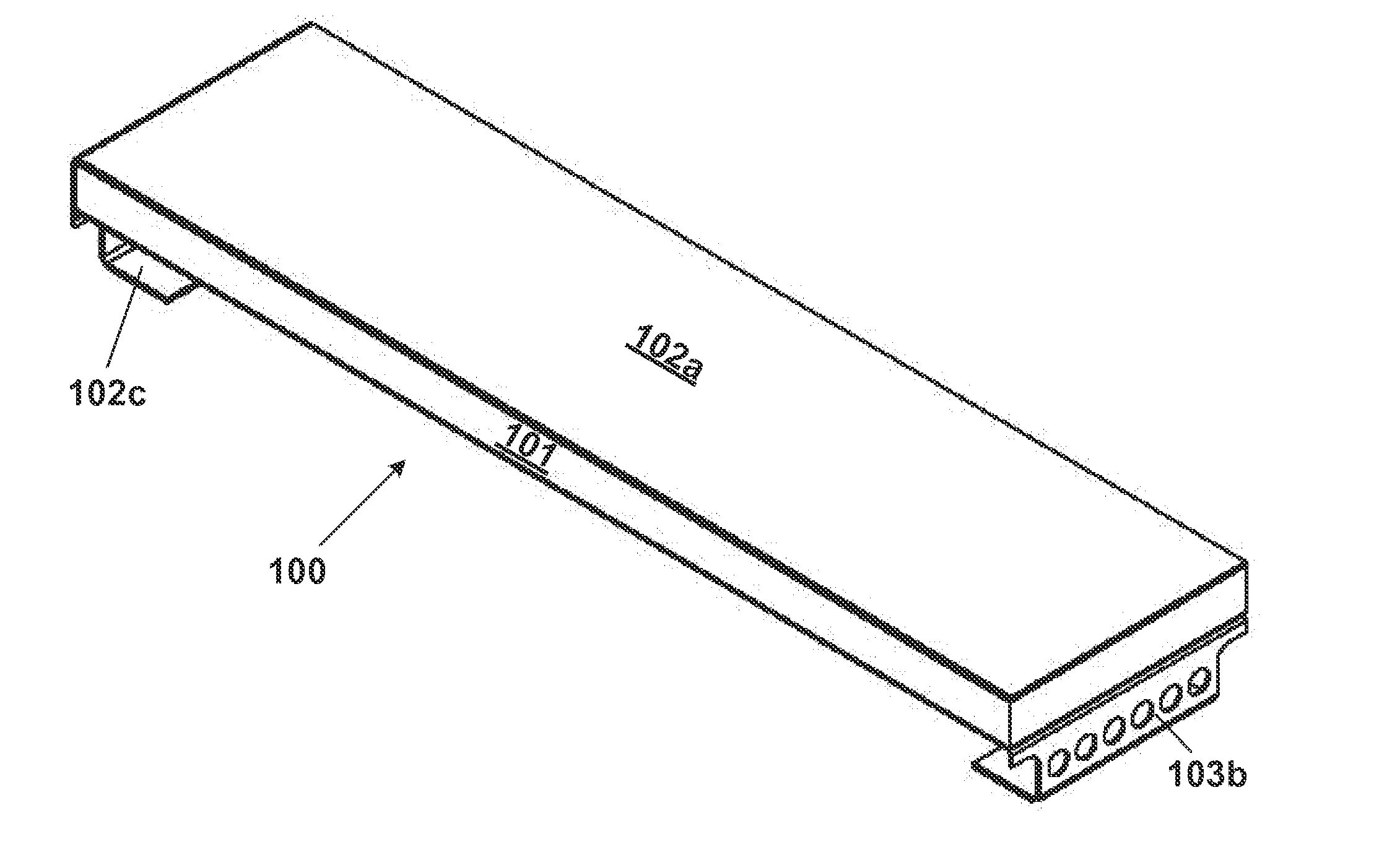
  • Solid state power source with frames for attachment to an electronic circuit
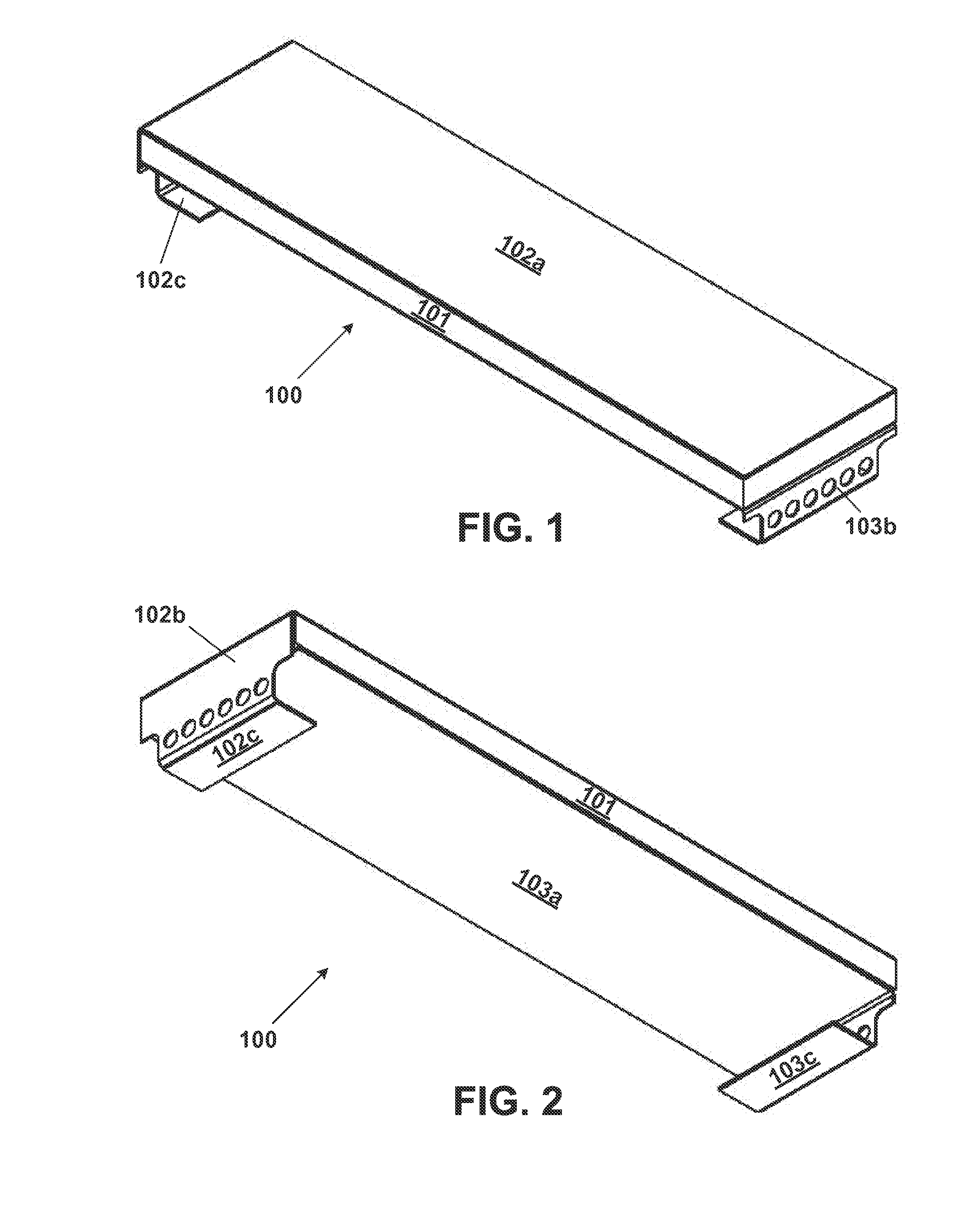
  • Solid state power source with frames for attachment to an electronic circuit
  • Solid state power source with frames for attachment to an electronic circuit

Examples


Embodiment Construction

[0038]Embodiments of the present invention are not limited to the particular methodology, compounds, materials, manufacturing techniques, uses, and applications described herein, as these may vary. It is also to be understood that the terminology used herein is used for the purpose of describing particular embodiments only, and is not intended to limit the scope of embodiments of the present invention. It must be noted that as used herein and in the appended claims, the singular forms “a,”“an,” and “the” include the plural reference unless the context clearly dictates otherwise. Thus, for example, a reference to “an element” is a reference to one or more elements, and includes equivalents thereof known to those skilled in the art. Similarly, for another example, a reference to “a step” or “a means” is a reference to one or more steps or means and may include sub-steps or subservient means. All conjunctions used are to be understood in the most inclusive sense possible. Thus, the wor...


PUM

PropertyMeasurementUnit
Poweraaaaaaaaaa
Electrical conductoraaaaaaaaaa

Abstract

A power source for a solid state device includes: a first frame having a first contact portion, a first bonding portion and a first extension portion between the first contact portion and the first bonding portion; a second frame having a second contact portion, a second bonding portion and a second extension portion between the second contact portion and the second bonding portion; and a first pole layer, an electrolyte layer and a second pole layer positioned between the first and second contact portions, wherein a first portion of the electrolyte layer is positioned between the first extension and the first pole and a second portion of the electrolyte layer is positioned between the first extension and the second pole.

Description

BACKGROUND OF THE INVENTION[0001]1. Field of the Invention[0002]The embodiments of the invention relate to a solid state power source, and more particularly, for example, to a solid state power source with frames for attachment to an electronic circuit. Although embodiments of the invention are suitable for a wide scope of applications, it is particularly suitable for powering an electronic circuit in an implant device in which both the solid state power source and the electronic circuit are hermetically sealed in an enclosure.[0003]2. Discussion of the Related Art[0004]In general, a conventional type of solid state power source includes a metallic battery encasement surrounding the bare structure of an electrochemical cell. The metallic battery encasement can include top and bottom metal shells, which are insulated from one another. The sides of the electrochemical cell are each respectively contacted by one of the top and bottom metal shells. An electrochemical cell can be a compo...

Claims


Application Information

Patent Timeline
IPC IPC(8): H01M2/02H01M50/103
CPCH01M2/0202A61N1/378H01M6/181H01M10/0427H01M10/4257H01M2220/30H01M10/0486Y10T428/24331H01M10/0436Y02E60/10H01M50/124H01M50/1245Y02P70/50H01M50/103H01M10/056
Inventor DAY, JOHN K.BARROR, MICHAEL W.SNYDER, SHAWN W.LAGUARDIA, ALEXANDRA Z.LYTLE, DAMON E.NEUDECKER, BERND J.
Owner MEDTRONIC INC
Why Eureka
Eureka Blog
Learn More