Oxide superconductor wire and superconducting coil

a superconductor wire and superconducting coil technology, applied in the direction of superconducting magnets/coils, cables, magnetic bodies, etc., can solve the problems of difficult winding of the release material layer, deterioration of superconductivity,

Active Publication Date: 2014-06-05
THE FUJIKURA CABLE WORKS LTD
View PDF7 Cites 12 Cited by
  • Summary
  • Abstract
  • Description
  • Claims
  • Application Information

AI Technical Summary

Benefits of technology

[0341]The oxide superconductor wire may be a long member having a length of several tens to several hundreds of meters according to the purpose.
[0342]Therefore, in a production field where a site area is limited, it is necessary that various kinds of coating treatments and operations be performed while changing a transport direction.
[0343]Accordingly, it is necessary that the transport direction be changed using the roller and the guide member illustrated in FIG. 8.

Problems solved by technology

As a result, after forming the superconducting coil, superconductivity may deteriorate.
However, from the viewpoint of coiling workability, it is difficult to wind the release material layer 102 having a thickness of approximately 10 μm or less along with the superconductor wire during coiling.

Method used


Image

  • Oxide superconductor wire and superconducting coil
  • Oxide superconductor wire and superconducting coil
  • Oxide superconductor wire and superconducting coil

Examples


first embodiment

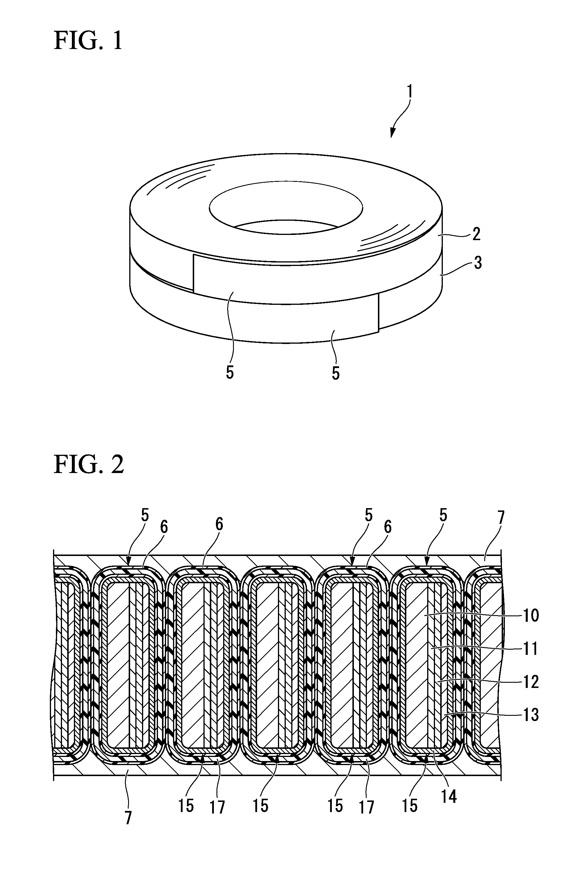
[0079]FIG. 1 illustrates a superconducting coil 1 which is formed by winding an oxide superconductor wire according to a first embodiment of the present invention. In this example, the superconducting coil 1 is formed as a two-layer pancake coil in which a pancake coil body 2 on an upper side and a pancake coil body 3 on a lower side are laminated.

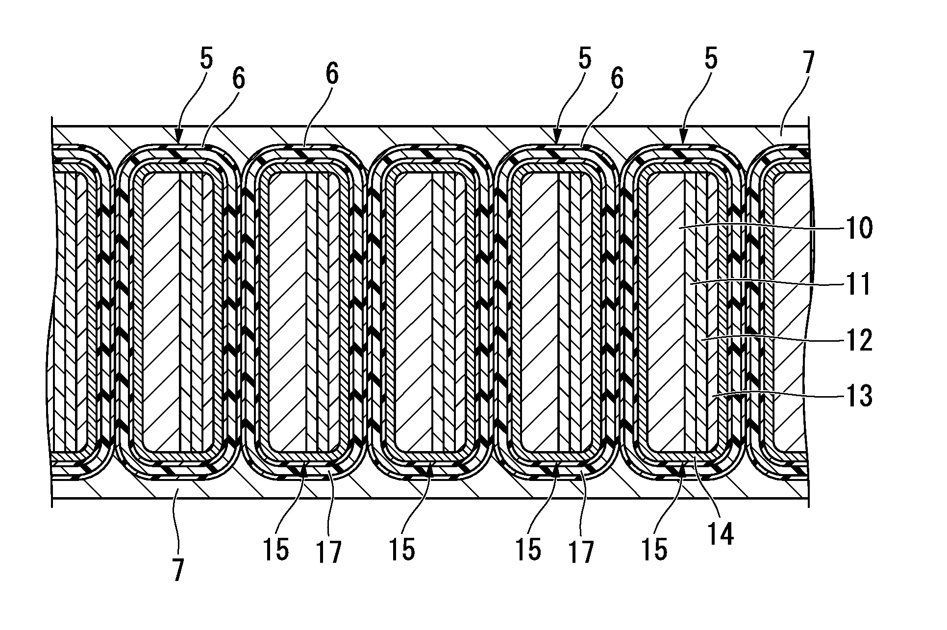
[0080]Each of the coil bodies 2 and 3 is formed by winding a tape-shaped oxide superconductor wire 5 having a cross-sectional structure illustrated in FIG. 2 in a spiral shape such that one surface thereof is an inside surface and the other surface is an outside surface.

[0081]In the example of FIG. 1, the coil body 2 on the upper side is formed by winding the oxide superconductor wire 5 clockwise, and the coil body 3 on the lower side is formed by winding the oxide superconductor wire 5 counterclockwise.

[0082]In addition, as illustrated in FIG. 2, the oxide superconductor wire 5 is provided with a coating layer 6 described below on the out...

second embodiment

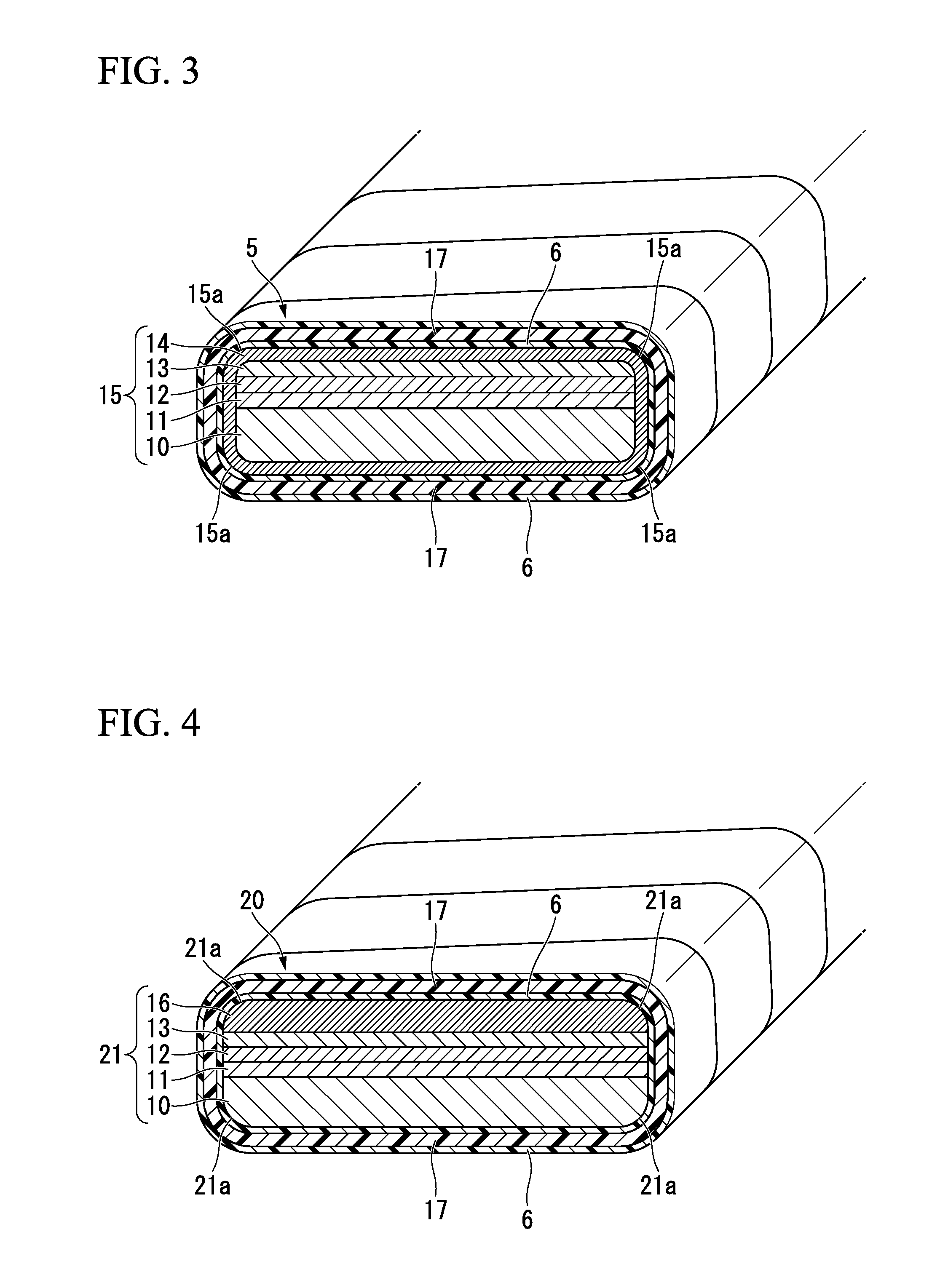
[0185]FIG. 4 is a cross-sectional perspective view illustrating part of an oxide superconductor wire for forming a superconducting coil according to a second embodiment of the present invention.

[0186]An oxide superconductor wire 20 having a cross-sectional structure illustrated in FIG. 4 includes a superconductor laminate 21 that is formed by laminating the intermediate layer 11, the oxide superconductor layer 12, the first metal stabilizing layer 13, and a second metal stabilizing layer 16 on one surface of the tape-shaped substrate 10; the insulating coating layer 17 that is provided with a coating layer and is formed so as to cover the entire outside surface of the superconductor laminate 21; and the coating layer 6 that is formed on both inside and outside surfaces of the insulating coating layer 17.

[0187]In addition, the first metal stabilizing layer 13 is laminated on only the oxide superconductor layer 12, and the second metal stabilizing layer 16 is laminated on only the fir...

third embodiment

[0212]FIG. 5 is a cross-sectional perspective view illustrating part of an oxide superconductor wire for forming a superconducting coil according to a third embodiment of the present invention.

[0213]An oxide superconductor wire 23 having a cross-sectional structure illustrated in FIG. 5 includes a superconductor laminate 25 that is formed by forming the intermediate layer 11, the oxide superconductor layer 12, and the first metal stabilizing layer 13 on one surface of the tape-shaped substrate 10 and forming a second metal stabilizing layer 24 so as to cover a circumference of the resultant; and the insulating coating layer 17 that is formed so as to cover the entire outside surface of the superconductor laminate 25.

[0214]In addition, the insulating coating layer 17 includes the coating layer 6, and the coating layer 6 is formed on both inside and outside surfaces of the insulating coating layer 17.

[0215]In this embodiment, the first metal stabilizing layer 13 is formed on only the ...


PUM

PropertyMeasurementUnit
critical temperatureaaaaaaaaaa
thicknessaaaaaaaaaa
thicknessaaaaaaaaaa

Abstract

An oxide superconductor wire includes: a superconductor laminate that comprises a substrate which is formed in a tape shape and an intermediate layer, an oxide superconductor layer, and a metal stabilizing layer which are laminated on the substrate; and an insulating coating layer that covers an outside surface of the superconductor laminate, Also, either the entire outside surface or the entire inside surface of the insulating coating layer is coated with a coating layer formed of a fluororesin.

Description

CROSS REFERENCE TO RELATED APPLICATIONS[0001]This application is a continuation in part application based on a PCT Patent Application No. PCT / JP2013 / 065938, filed Jun. 10, 2013, whose priority is claimed on Japanese Patent Application No. 2012-131927, filed Jun. 11, 2012, the entire content of which are hereby incorporated by reference.BACKGROUND OF THE INVENTION[0002]1. Field of the Invention[0003]The present invention relates to an oxide superconductor wire and a superconducting coil.[0004]2. Description of the Related Art[0005]A metal superconductor wire such as NbTi which is used in the conventional art is provided, for example, in round or angular form, and the degree of freedom for the shape thereof is high.[0006]On the other hand, in an oxide superconductor of Bi (bismuth), Y (yttrium), or the like in which a critical temperature is approximately 90 K to 100 K, an oxide superconductor layer is formed of a ceramic.[0007]In addition, it is preferable that the structure of a wir...

Claims


Application Information

Patent Timeline
Patent Type & Authority Applications(United States)
IPC IPC(8): H01F6/06H01B12/02
CPCH01F6/06H01B7/00H01B12/02H01B3/445H01B3/308H10N60/203H01B12/00
Inventor DAIBO, MASANORI
Owner THE FUJIKURA CABLE WORKS LTD
Why Eureka
Try Eureka