Self aligning split mechanical seal employing a selectively engageable axial biasing assembly

a split mechanical seal and selective engagement technology, applied in the field of sealing assemblies, can solve the problems of difficulty often encountered, prior art split mechanical seal assembly designs posed several problems, and the rotary seal face of prior art mechanical seal assembly designs has a tendency to pop out after being inserted, so as to achieve convenient relative alignment

Active Publication Date: 2014-06-12
A W CHESTERTON
View PDF11 Cites 14 Cited by
  • Summary
  • Abstract
  • Description
  • Claims
  • Application Information

AI Technical Summary

Benefits of technology

[0011]It is therefore an object of the present invention to provide a split mechanical seal that employs rotary and stationary seal ring segments that can be easily aligned relative to each other.
[0012]It is also an object of the present invention to provide a split mechanical seal that employs structure that can selectively remove the axial biasing force applied to the one of the seal rings, such as for example the stationary seal ring, during installation.
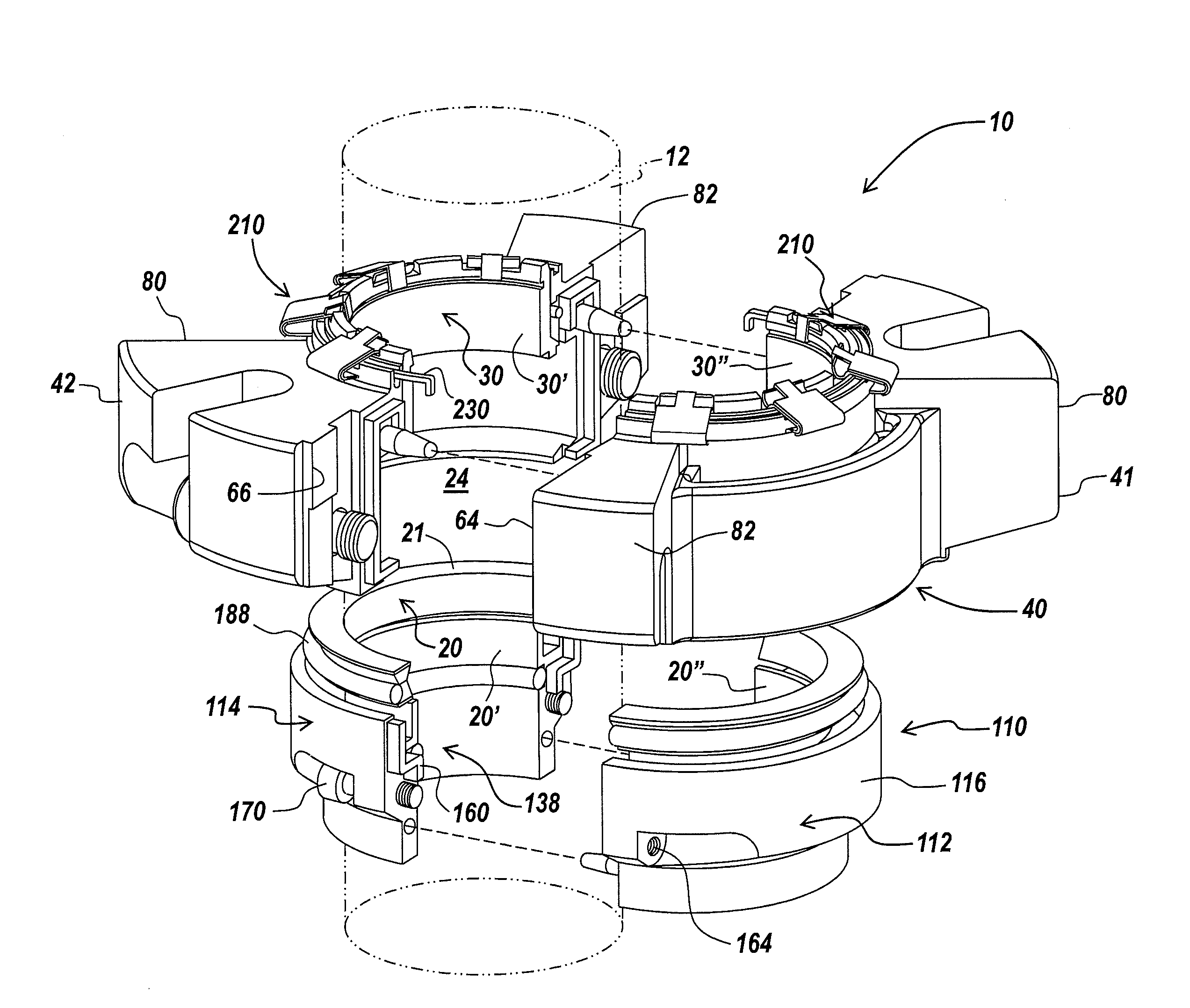
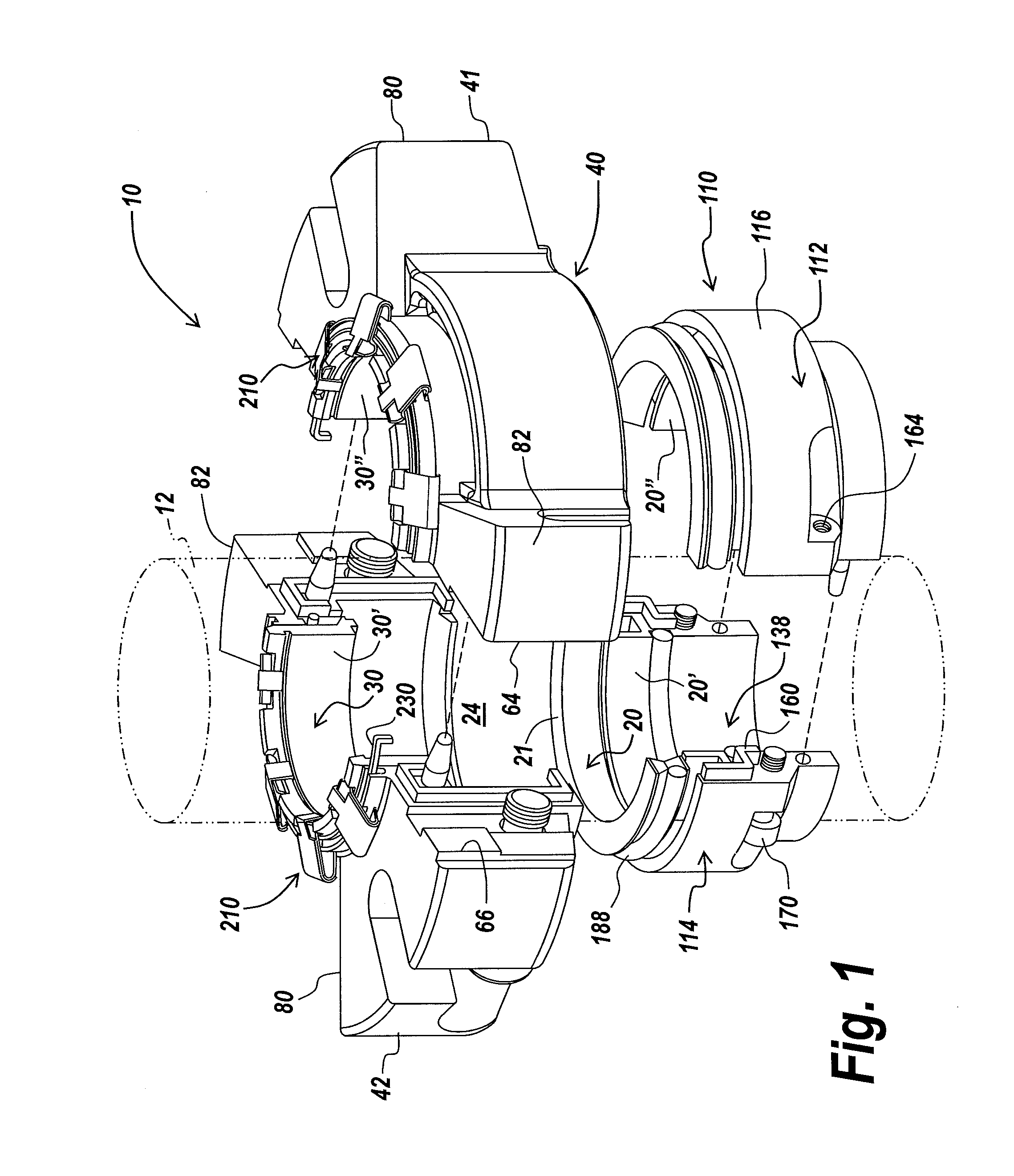
[0014]The mechanical seal of the present invention also provides for split seal ring components that have non-flat, axially extending seal ring faces that interlock with the corresponding seal ring face on the opposed seal ring segment. When placed together, the seal ring segments interlock and are hence self-aligning. The non-flat nature of the axial seal ring faces of the seal ring segments enables the segments to interact with each other in such a manner as to facilitate engagement of the segments with each other while concomitantly reducing or preventing sliding of the segments relative to each other.
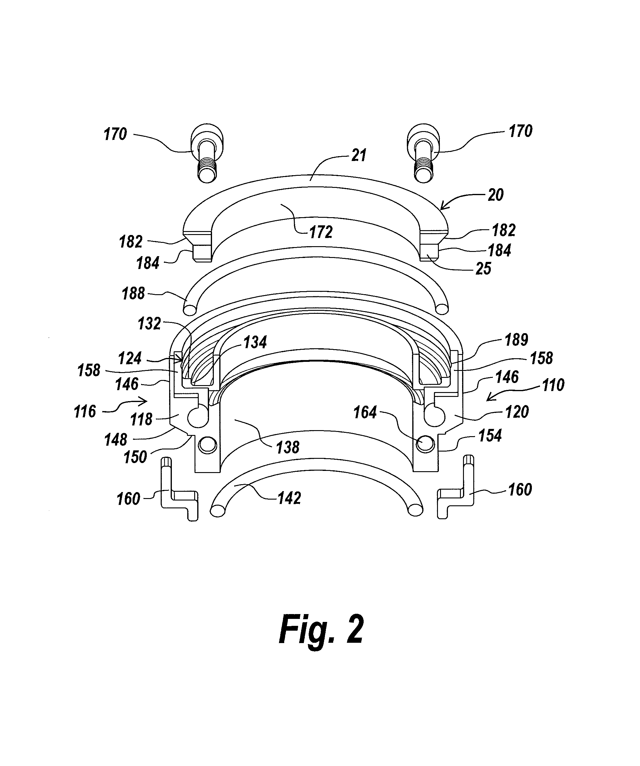
[0015]The split mechanical seal also includes a holder assembly for seating and retaining the rotary seal ring element. The holder assembly has a pair of arcuate holder segments that are retained together with known fastening mechanisms. The holder segments each have a stepped radially inner surface on the annular body, where the radially inner surface includes a detent groove for allowing easy insertion of and seating an O-ring.
[0016]The split mechanical seal assembly of the present invention also includes a gland assembly having interacting, mating halves to facilitate engagement of the gland halves and to reduce or prevent sliding of the gland halves relative to each other when forces from the bolts, the equipment housing, the gasket support and / or other sources are applied to the gland assembly.
[0017]The gland assembly includes on the axially upper most or top surface a gland groove that houses in each gland segment a movable spring engaging mechanism that serves to selectively engage and disengage the biasing mechanism (i.e., clips). When disposed in the engaged position, the movable member engages the biasing element and removes the axial biasing force applied by the biasing element to the stationary seal ring. This biasing removal feature thus enables the installer to readily and easily install the seal rings around the shaft while minimizing any contact damage to the rings that may occur. When disposed in the disengaged position, the movable member moves within the groove to disengage from the biasing element, thus allowing the biasing members to engage the stationary seal ring and to apply an axially biasing force thereto. This axial biasing force serves to place the seal face of the stationary seal ring into sealing engaged contact with the seal face of the rotary seal ring.

Problems solved by technology

Previous split mechanical seal designs posed several problems.
A first problem with prior split mechanical seal designs relates to the insertion of the rotary seal ring into the holder assembly that is clamped around the shaft.
The rotary seal face must be pushed into a tight space inside the clamped holder, and some difficulty may often be encountered.
In addition, since the O-ring tends to grab the seal ring and inhibits sliding, the rotary seal face of prior art mechanical seal assembly designs has a tendency to “pop-out” after being inserted.
Further, the movement of the O-ring when installed can result in the O-ring being disposed in an angled position, rather than a more preferred seated position relative to the rotary seal ring.
From the angled position, the installer would be required to move the O-ring back to the original position, which is quite difficult to do.
If significant enough, this can result in shortened seal life.
A further problem exists when the installer is assembling the mechanical seal around the shaft at the installation site.
It is quite difficult for the installer to keep the rotary seal ring halves aligned relative to each other.
Similarly, it is also difficult for the installer to keep the stationary seal ring halves aligned.
As the remainder of the mechanical seal assembly is placed about the seal rings, the biasing mechanisms prematurely force the seal rings into contact with each other.
The consequence of these various issues is that the seal rings are constantly coming into forceful contact with each other, which often results in damage to the seal rings.
Moreover, since the axial split surfaces of the seal ring halves are relatively smooth and flat, it is also difficult for the installer to keep the faces aligned during installation.

Method used


Image

  • Self aligning split mechanical seal employing a selectively engageable axial biasing assembly
  • Self aligning split mechanical seal employing a selectively engageable axial biasing assembly
  • Self aligning split mechanical seal employing a selectively engageable axial biasing assembly

Examples


Embodiment Construction

[0036]The present invention provides a mechanical seal assembly for providing sealing on a rotating shaft or other suitable device. The invention will be described below relative to illustrated embodiments. Those skilled in the art will appreciate that the present invention may be implemented in a number of different applications and embodiments and is not specifically limited in its application to the particular embodiment depicted herein.

[0037]The terms “seal assembly” and “sealing assembly” as used herein are intended to include various types of sealing assemblies, including single seals, split seals, concentric seals, spiral seals, and other known seal and sealing assembly types and configurations.

[0038]The term “shaft” is intended to refer to any suitable device in a mechanical system to which a seal can be mounted and includes shafts, rods and other known devices.

[0039]The terms “axial” and “axially” used herein refer to a direction generally parallel to the axis of a shaft. T...


PUM

PropertyMeasurementUnit
obtuse angleaaaaaaaaaa
angleaaaaaaaaaa

Abstract

A split mechanical seal for mounting to a housing containing a rotating shaft comprising a gland assembly configured for mounting to the housing and forming a chamber, where the gland assembly includes a top surface having a gland groove formed thereon. The gland groove is formed at least in part by at least one raised wall portion that extends axially outwardly from the top surface. The seal also includes a stationary seal ring having a groove or recess formed in an inner surface.

Description

RELATED APPLICATION[0001]This application claims priority to U.S. provisional patent application Ser. No. 61 / 734,691, filed on Dec. 07, 2012, entitled Self Aligning Split Mechanical Seal Employing A Selectively Engageable Axial Biasing Assembly, the contents of which are hereby incorporated by reference. This application is also related to U.S. patent application Ser. No. 14 / 100,806, entitled Self Aligning Split Mechanical Seal Employing A Rotary Seal Ring Having Non-Flat End Faces, filed concurrently herewith, the contents of which are hereby incorporated by reference.FIELD OF THE INVENTION[0002]The present invention relates to a seal assembly for sealing a shaft or a rod relative to a stationary housing component. This invention relates generally to mechanical seals. More particularly, the present invention relates to universal split mechanical seals that provide for easy installation on various pump housings.BACKGROUND OF THE INVENTION[0003]Conventional mechanical seal assemblies...

Claims


Application Information

Patent Timeline
Patent Type & Authority Applications(United States)
IPC IPC(8): F16J15/34
CPCF16J15/3488Y10T29/49863Y10T29/49826F16J15/3464F16J15/38F16J15/3452F16J15/3472
Inventor CID, EDWINAZIBERT, HENRI V.ATTENASIO, ANN T.CONKLIN, TIMOTHYPHILLIPS, HOWARD
Owner A W CHESTERTON
Why Eureka
Try Eureka