
Adaptive sidelobe suppression of radar transmit antenna pattern

a technology of transmit antenna and sidelobe, applied in the field of radar transmission, can solve the problems of increasing the convergence time of the loop, affecting the uniformity of the response of the sidelobe throughout the bandwidth,

Inactive Publication Date: 2014-06-12
SRC INC
View PDF3 Cites 15 Cited by
  • Summary
  • Abstract
  • Description
  • Claims
  • Application Information

AI Technical Summary

Benefits of technology

The present invention is a method for generating a sidelobe null in a radar transmit antenna pattern. This is done by positioning a small air vehicle, such as a helicopter, along the radial from the radar that corresponds to the sidelobe to be nulled. The air vehicle is fitted with a receiver and antenna facing the radar, as well as a GPS device for maintaining the designated position. A communication link or transponder is used to form a closed loop with the main radar transmitter to adjust the attenuators and phase shifters of the auxiliary channels to suppress signals transmitted in the sideloe to be nulled. The method can be used in situations where a deep null must be maintained for a limited time. Additional auxiliary channels can be introduced to achieve a more uniform response, although this will increase the convergence time of the loop. The signals can also be transformed to the frequency domain and divided into subbands, with a distinct weight computed for each subband, and the nulling signals reconstructed from their subband constituents. Multiple simultaneous nulls can also be formed by using an additional air vehicle for each sidelobe to be nulled.

Problems solved by technology

Because of the finite bandwidth and possible large main antenna aperture, the sidelobe response may be non-uniform throughout the bandwidth.
However, these additional degrees-of-freedom introduced in the feedback path will increase the convergence time of the loop.

Method used


Image

  • Adaptive sidelobe suppression of radar transmit antenna pattern
  • Adaptive sidelobe suppression of radar transmit antenna pattern
  • Adaptive sidelobe suppression of radar transmit antenna pattern

Examples


Embodiment Construction

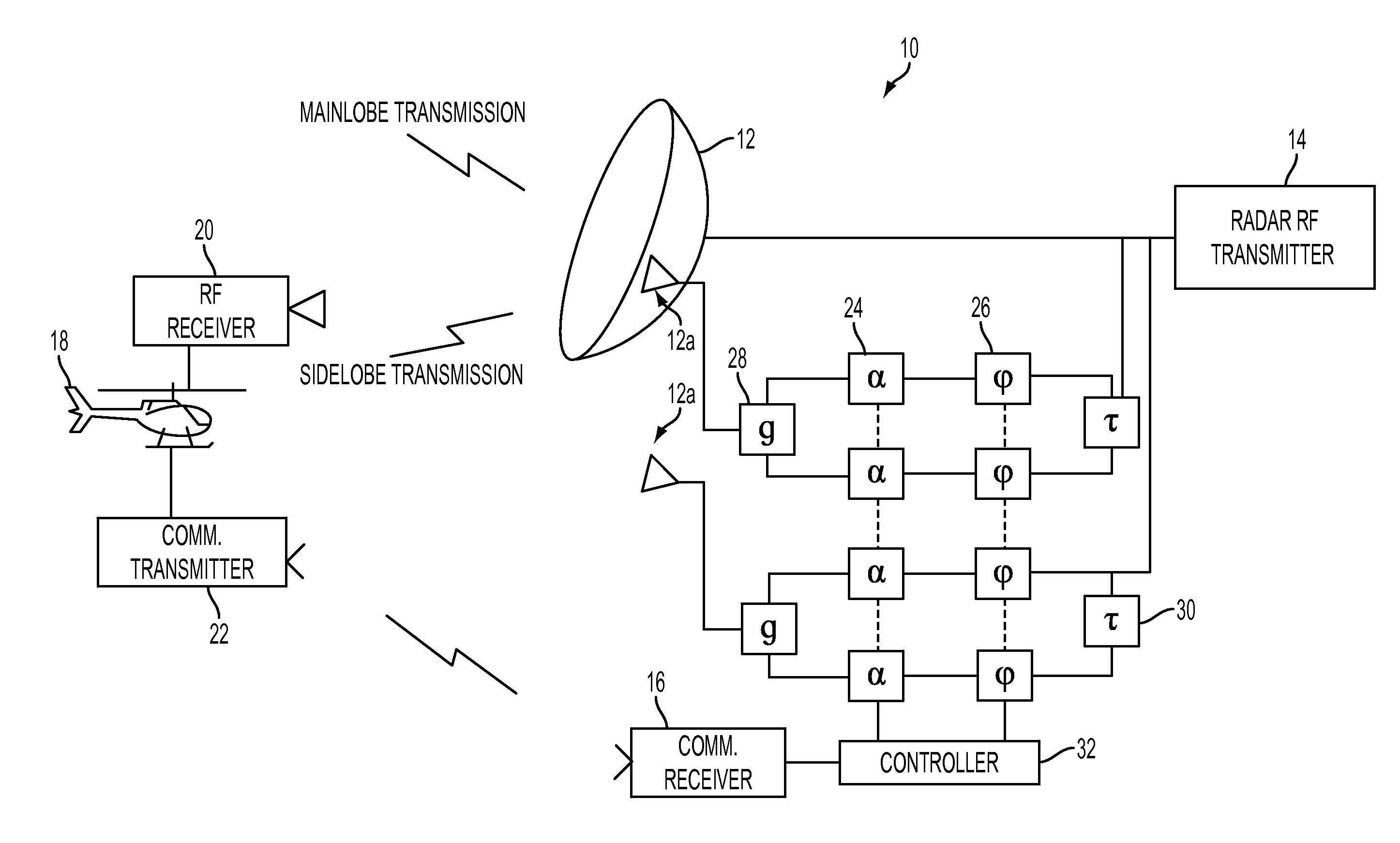
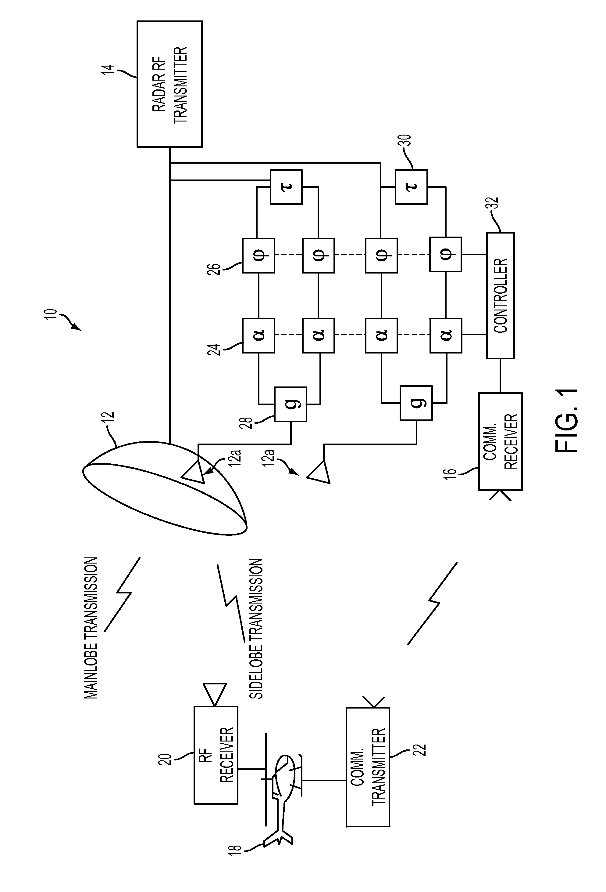
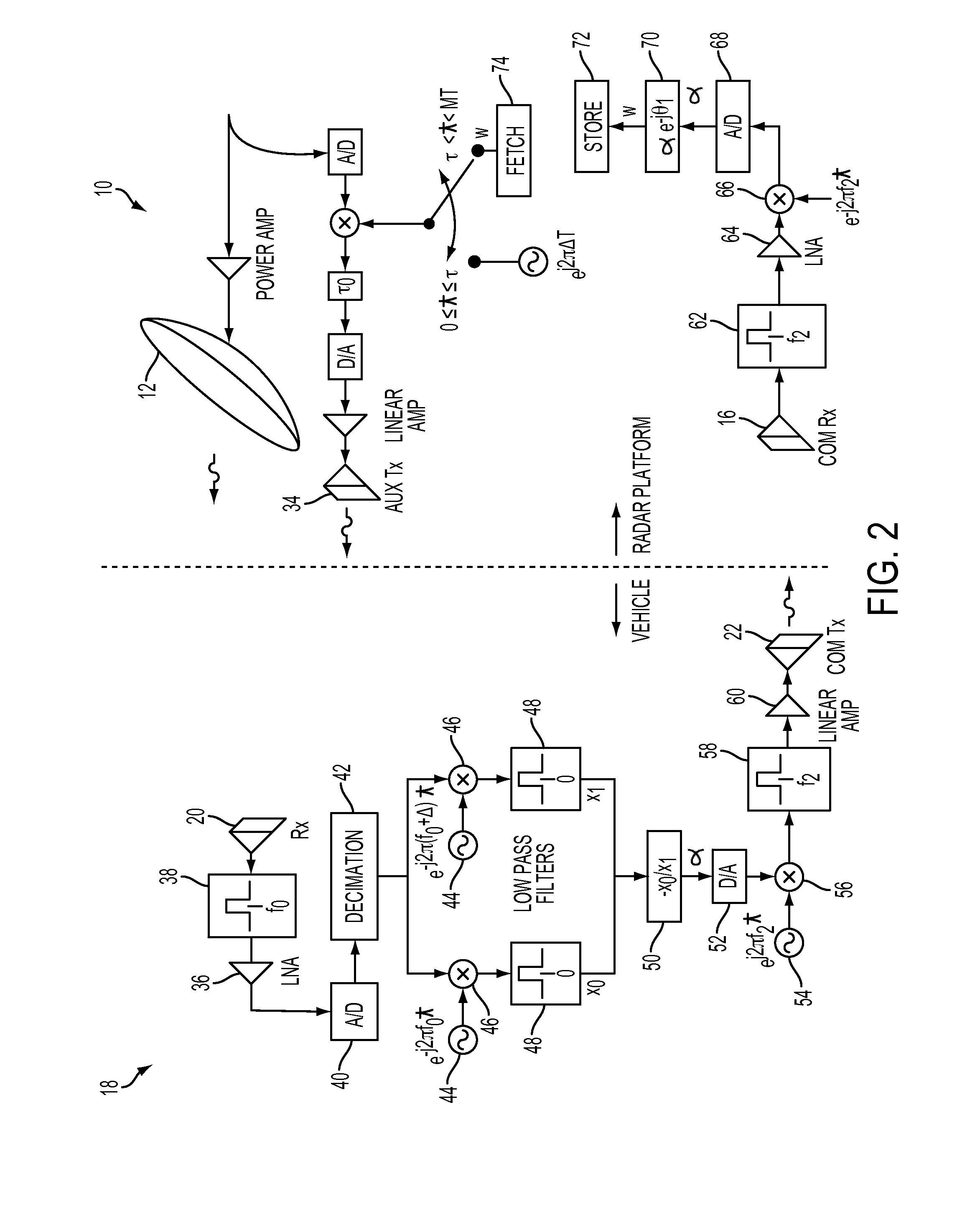
[0015]Referring now to the drawings, wherein like reference numerals refer to like parts throughout, there is seen in FIG. 1 a closed loop sidelobe transmission nulling system 10 comprising a main transmission radar 12 having a radar transmitter 14, two auxiliary transmit systems 12a, and a communication receiver 16, along with a remotely positioned aircraft or air vehicle 18 having an RF receiver 20 and a communication transmitter 22 for communicating with communication receiver 16 of auxiliary system 12a. Vehicle 18 is preferably positioned at close range to radar 12, but just beyond its far field boundary. As an alternative, communication transmitter 22 can be replaced with a transponder located on the vehicle. That replacement would shift more of the signal processing to the main radar platform, as described in more detail below and shown in FIGS. 2 and 3.

[0016]As further seen in FIG. 1, auxiliaries 12a include an electronics assembly having a plurality of variable attenuators 2...


PUM


Abstract

A system for adaptively generating a sidelobe null in a radar transmit antenna pattern by positioning a small air vehicle along the radial of the sidelobe to be suppressed. The air vehicle is fitted with a receiver and antenna facing the radar, as well as a GPS device for maintaining the designated position. The vehicle further includes a communication link to the processor of the main radar transmitter to form a closed loop that enables adjustment of the attenuators and phase shifters of the auxiliary channel(s) to suppress signals transmitted in the sidelobe to be nulled. The com link may be replaced by a suitable transponder.

Description

STATEMENT OF GOVERNMENT INTEREST[0001]This work derives from research under Government Contract W15P7T-08-C-V004. The U.S. Government has rights in this invention.BACKGROUND OF THE INVENTION[0002]1. Field of the Invention[0003]The present invention relates to radar transmissions and, more particularly, to the suppression of sidelobe signals.[0004]2. Description of the Related Art[0005]Radar applications often require that the energy that is transmitted in certain directions be reduced the amount typically transmitted by the radar antenna sidelobes. One method of reducing sidelobe transmission is to simultaneously transmit a nearly equal and opposite signal through an auxiliary antenna. The amplification (or attenuation) and phase applied to the signal in the auxiliary channel, or channels, if a broad angle and / or wide band null is desired, to achieve cancelation are determined from knowledge of the complex antenna pattern of the main antenna, i.e., the amplitude and phase patterns. ...

Claims


Application Information

Patent Timeline
IPC IPC(8): G01S7/02
CPCG01S7/2813
Inventor SCHUMAN, HARVEY K.
Owner SRC INC
Learn More