
Method for introducing light shield partial increment magnification coefficient into optical proximity effect model building

A technology of optical proximity effect and amplification factor, which is applied in optics, microlithography exposure equipment, special data processing applications, etc., can solve the problems of wasting modeling and fitting time, poor accuracy, non-convergence, etc., and achieve good physical Significance, effects of speeding up fitting and convergence time

Active Publication Date: 2009-04-01
SHANGHAI HUAHONG GRACE SEMICON MFG CORP
View PDF0 Cites 5 Cited by
  • Summary
  • Abstract
  • Description
  • Claims
  • Application Information

AI Technical Summary

Problems solved by technology

Therefore, how to take into account the process measurement error and the specific structure with large process deviation before the real model is established is the direction of research, without the need to pass a large number of silicon wafer verifications of two-dimensional graphics after running the long process of modeling To test the reliability and predictability of the model and then readjust the modeling process to waste a lot of modeling and fitting time, and it can also avoid modeling from the beginning to a mathematical rather than physical process model, resulting in Subsequent non-convergent, unreliable and poorly accurate process models

Method used

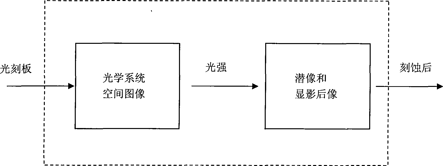
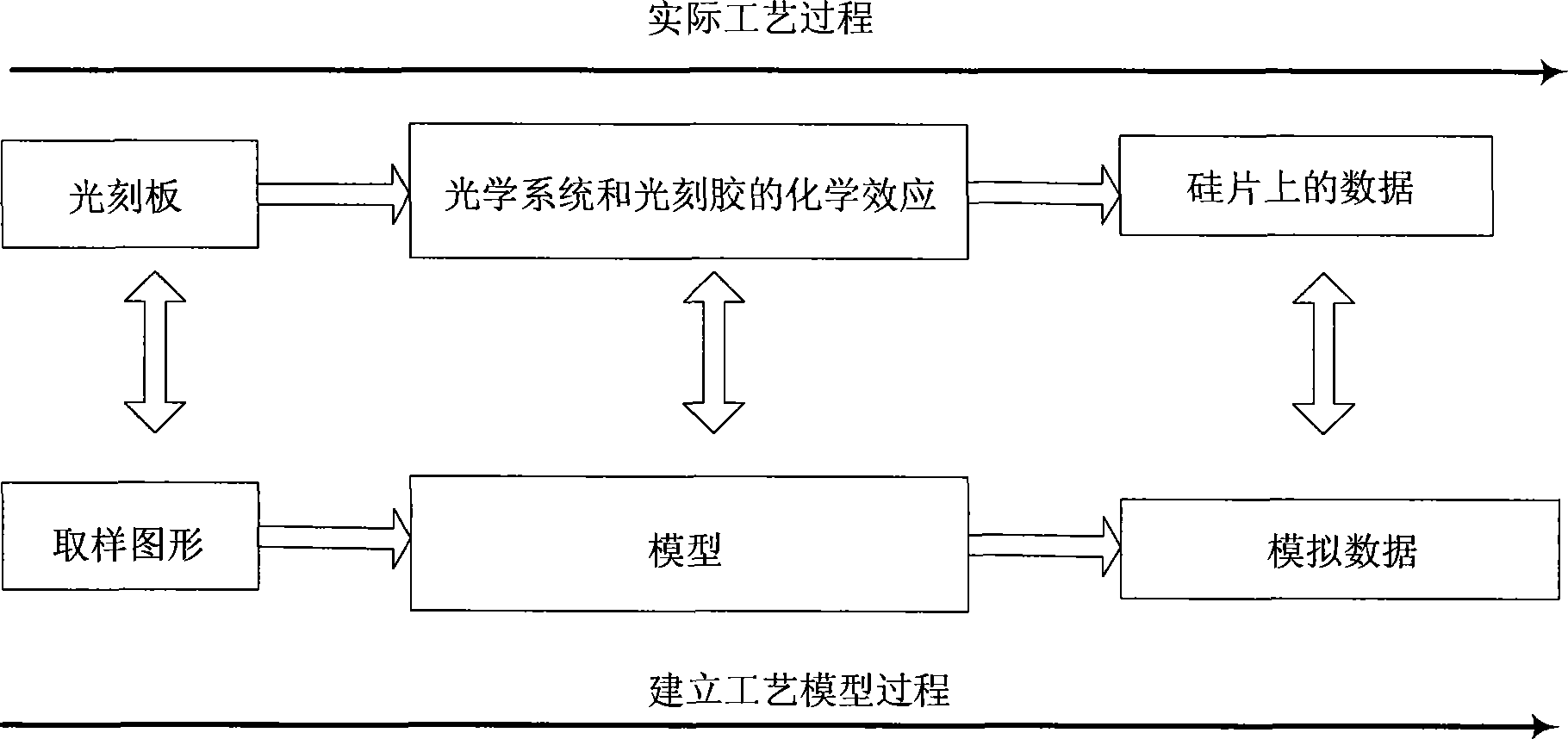
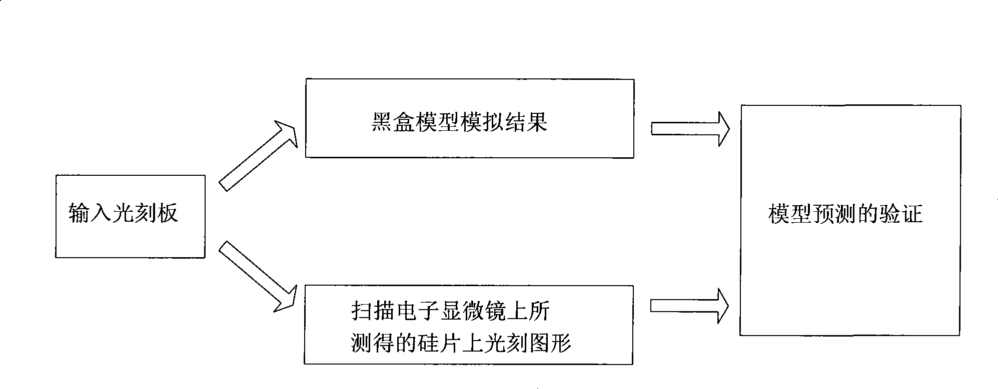

Image

  • Method for introducing light shield partial increment magnification coefficient into optical proximity effect model building
  • Method for introducing light shield partial increment magnification coefficient into optical proximity effect model building
  • Method for introducing light shield partial increment magnification coefficient into optical proximity effect model building

Examples


Embodiment Construction

[0022] A reasonable process model should be dominated by the physical model. In the process of establishing the process model, a stable physical optical model must be established first, so that the feature size that may be caused by changes in the optical environment can be well predicted.

[0023] The present invention provides a parameter and method of weight. In the process of collecting the basic process line width data of the process model of the optical proximity effect process, the mask deviation amplification factor MEEF of a specific figure is used.

[0024] Correlate the empirical linewidth data required by the process model with the mask deviation amplification factor MEEF:

[0025] W=W(MEEF)

[0026] In this way, we can filter some unstable factors in the process and measurement, greatly speeding up the fitting and convergence time of the process model establishment, while ensuring the accuracy, reliability and stability of the process model.

[0027] Similarly, i...


PUM


Abstract

The invention discloses a method for leading a photo mask deviation magnification coefficient into optical proximity effect modeling, and during collection of line width data for a basic process of optical proximity effect, a process model is built, a weight value of experienced line width data required by the process model is correlated with the photo mask deviation magnification coefficient of a graphics, so that a plurality of processes and unstable factors in measurement can be filtered, and the fitting and convergence time for building the process model can be greatly accelerated, meanwhile, the accuracy and reliable stability of the process model can be ensured.

Description

technical field [0001] The invention relates to a method for modeling optical proximity effect, in particular to a method for introducing a mask deviation amplification factor into optical proximity effect modeling. Background technique [0002] As the feature size of semiconductor chips gradually shrinks, the photolithography process faces more challenges. The well-known optical proximity effect has become a non-negligible fabrication effect below 0.18 microns. Usually the optical proximity effect correction is used to compensate the pattern distortion caused by the optical proximity effect, and the feature size deviation caused by the optical proximity effect at 0.15 microns and above accounts for a small proportion compared to the design rules. Therefore, it is sufficient to use the rule-based optical proximity correction to compensate for the distortion of the graphics caused by the optical proximity effect. However, fabrication below 0.13 microns results in feature si...

Claims


Application Information

Patent Timeline
Patent Type & Authority Applications(China)
IPC IPC(8): G06F17/50G03F1/14G03F7/20G03F1/36
Inventor 陈福成张斌魏芳
Owner SHANGHAI HUAHONG GRACE SEMICON MFG CORP
Learn More