Apparatus and method for providing information of blind spot

a technology of blind spot and information, applied in the field of apparatus and a blind spot information method, can solve the problems of blind spot, driver's inability to check whether obstacles exist, measurement error of sensors, etc., and achieve the effect of improving the detection accuracy of object location, improving object detection accuracy, and improving object detection accuracy

Inactive Publication Date: 2014-06-12
HYUNDAI MOTOR CO LTD
View PDF6 Cites 15 Cited by
  • Summary
  • Abstract
  • Description
  • Claims
  • Application Information

AI Technical Summary

Benefits of technology

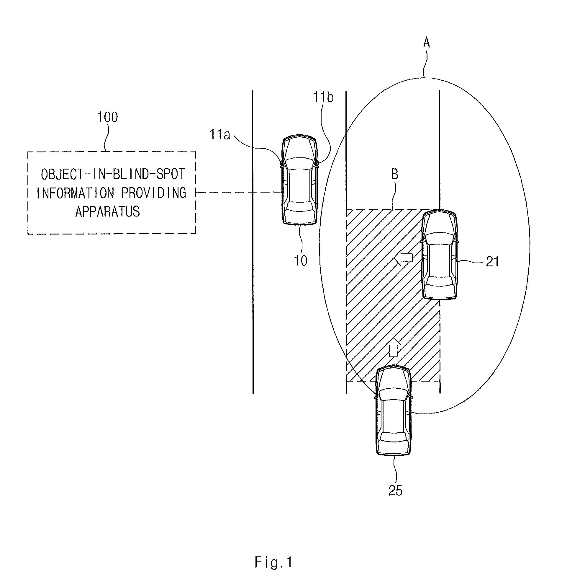
[0020]According to another exemplary embodiment, the controller may be configured to detect an object in a side area and a rear side area disposed in a blind spot from an image of a wide angle side imaging device, thereby improving object detection in the blind spot.
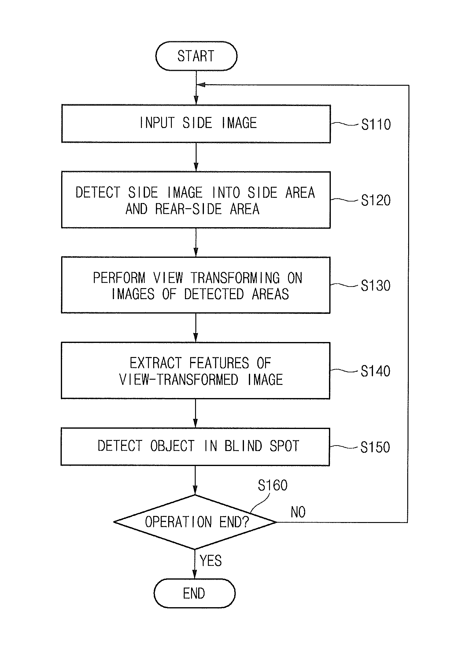
[0021]In particular, the present disclosure designates a side area and a rear side area in which shape change is minimized according to location of an object in one side image and view transform images of two designated areas, thereby increasing object detection accuracy. Further, the controller in present disclosure may be configured to extract features from the images into which the images of the side area and the rear side area divided from the image of the wide angle side imaging device is view transformed to detect the object in the blind spot, thereby improving detection accuracy of object location.

Problems solved by technology

However, a blind spot, which may not be monitored using the side mirror, exists due to a limited available range of the side mirror.
Therefore, drivers may be unable to check whether obstacles exists in the area of the blind spot.
However, a separate sensor must be attached to the vehicle and a measurement error of the sensor occurs due to an effect of external environments and the characteristic of the sensor itself.

Method used


Image

  • Apparatus and method for providing information of blind spot
  • Apparatus and method for providing information of blind spot
  • Apparatus and method for providing information of blind spot

Examples


Embodiment Construction

[0028]Although exemplary embodiment is described as using a plurality of units to perform the exemplary process, it is understood that the exemplary processes may also be performed by one or plurality of modules. Additionally, it is understood that the term controller refers to a hardware device that includes a memory and a processor. The memory is configured to store the modules and the processor is specifically configured to execute said modules to perform one or more processes which are described further below.

[0029]Furthermore, control logic of the present invention may be embodied as non-transitory computer readable media on a computer readable medium containing executable program instructions executed by a processor, controller or the like. Examples of the computer readable mediums include, but are not limited to, ROM, RAM, compact disc (CD)-ROMs, magnetic tapes, floppy disks, flash drives, smart cards and optical data storage devices. The computer readable recording medium ca...


PUM


Abstract

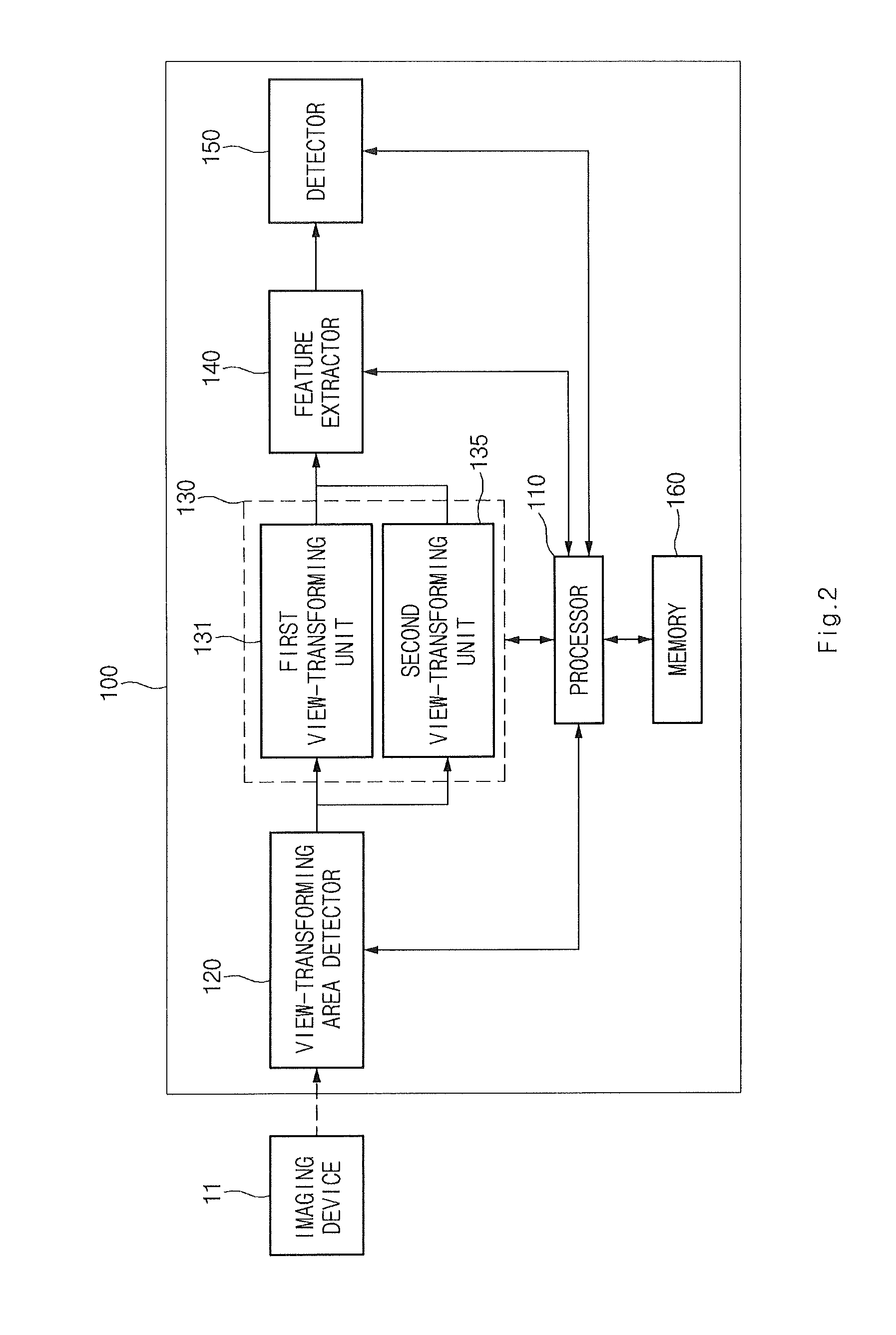
Disclosed is an apparatus and method for providing information regarding a blind spot in a vehicle. The apparatus includes a view transforming area detector that is configured to detect a predefined side area and rear side area from a captured image input from a side imaging device. The imaging device is configured to capture the image including the blind spot of the vehicle. Additionally, the apparatus includes a view transformer that is configured to view transform an image of the side area and an image of the rear side area based on a pre-set view transformation parameter and generate view transformed images corresponding to the images of the side area and the rear side area.

Description

CROSS-REFERENCES TO RELATED APPLICATIONS[0001]The priority of Korean patent application No. 10-2012-0144896 filed on Dec. 12, 2012, the disclosure of which is hereby incorporated in its entirety by reference, is claimed.BACKGROUND OF THE INVENTION[0002]1. Field of the Invention[0003]The present disclosure relates to an apparatus and a method for providing information regarding a blind spot in a vehicle, and more particularly, to technology which detects objects in a side area and a rear side area which are in a blind spot from a wide angle side image.[0004]2. Description of the Related Art[0005]In general, vehicle drivers check a rear side area of the vehicle through a side mirror. However, a blind spot, which may not be monitored using the side mirror, exists due to a limited available range of the side mirror. Therefore, drivers may be unable to check whether obstacles exists in the area of the blind spot.[0006]Thus, to determine whether an obstacle or object is present in the bli...

Claims


Application Information

Patent Timeline
Patent Type & Authority Applications(United States)
IPC IPC(8): G06K9/00G06V10/147
CPCG06V20/56G06V10/147B60R1/08B60R21/00B60W40/02G06V20/58
Inventor LEE, BYOUNG JOONJUNG, HO CHOULAN, JUN SIKSUNG, KAP JE
Owner HYUNDAI MOTOR CO LTD
Why Eureka
Try Eureka