Blind-spot monitoring using machine vision and precise FOV information

a technology of machine vision and blind spots, applied in the field of video capture devices, can solve problems such as accidents between vehicles, blind spots, blind spots, etc., and achieve the effect of improving object detection

Active Publication Date: 2018-04-03
AMBARELLA INT LP
View PDF5 Cites 6 Cited by
  • Summary
  • Abstract
  • Description
  • Claims
  • Application Information

AI Technical Summary

Benefits of technology

[0006]The objects, features and advantages of the present invention include providing blind-spot monitoring using machine vision and precise FOV information that may (i) determine a field of view of a driver, (ii) improve object detection in blind-zones, (iii) estimate a location of eyes of a driver, (iv) be implemented using existing in-car cameras, (v) warn a user of objects in blind spots, (vi) be implemented with various vehicle sensor systems, (vii) determine actual blind-spots of a driver, (viii) provide visual feedback about blind-zones and / or (ix) be easy to implement.

Problems solved by technology

Blind zones, or blind spots, in a vehicle are a leading cause of accidents between vehicles.
Studies show that a majority of drivers do not know how to align mirrors correctly.
Furthermore, when drivers use vehicles that are not their own, or use a shared vehicle, drivers often find the process of manual mirror adjustment of vehicle mirrors to be too bothersome for a single trip.
Current blind-spot detection systems are expensive (since they typically use radar), and tend to warn the user about vehicles that are in certain pre-determined zones around the vehicle.

Method used


Image

  • Blind-spot monitoring using machine vision and precise FOV information
  • Blind-spot monitoring using machine vision and precise FOV information
  • Blind-spot monitoring using machine vision and precise FOV information

Examples


embodiment 150

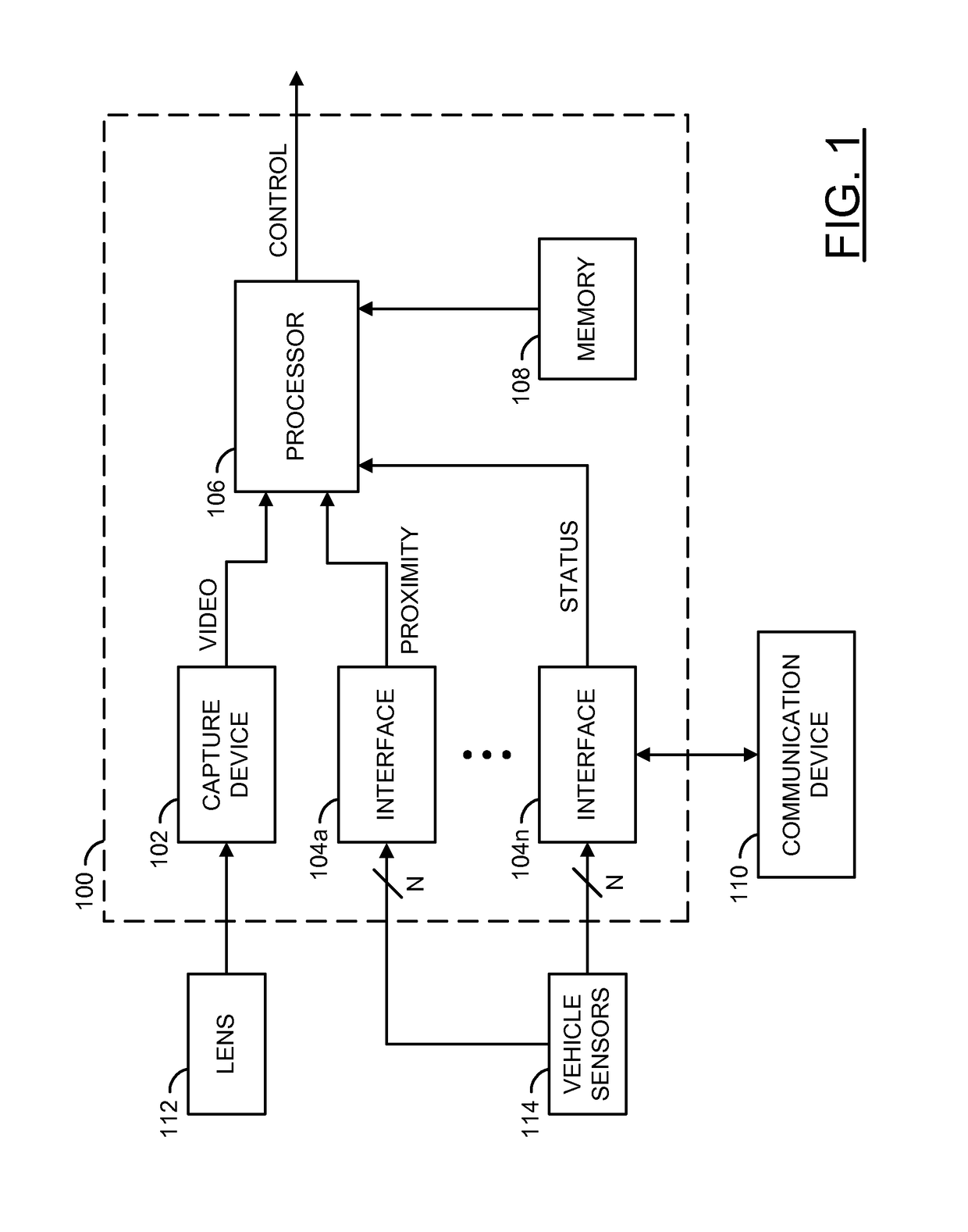
[0021]Referring to FIG. 3, an embodiment 150 illustrating the capture device 102 detecting the driver of an automobile / vehicle 50 is shown. The camera system 100 is shown inside the vehicle 50. The capture device 102 is shown inside the vehicle 50. A driver 152 is shown seated in the vehicle 50. A side view mirror 154 is shown attached to the vehicle 50. Sensors 114a-114b are shown on (or in) the vehicle 50.

[0022]The camera system 100 is shown in the rear of the vehicle 50. A location of the camera system 100 may be varied according to the design criteria of a particular implementation. For example, in some embodiments, the vehicle 50 may allow for installation of the camera system 100 in a rear end of the vehicle 50. In other embodiments, the vehicle 50 may allow for installation of the camera system 100 in a front end of the vehicle 50. For example, the camera system 100 may be installed near and / or with the capture device 102 (e.g., in a dashboard of the vehicle 50). In another e...

embodiment 200

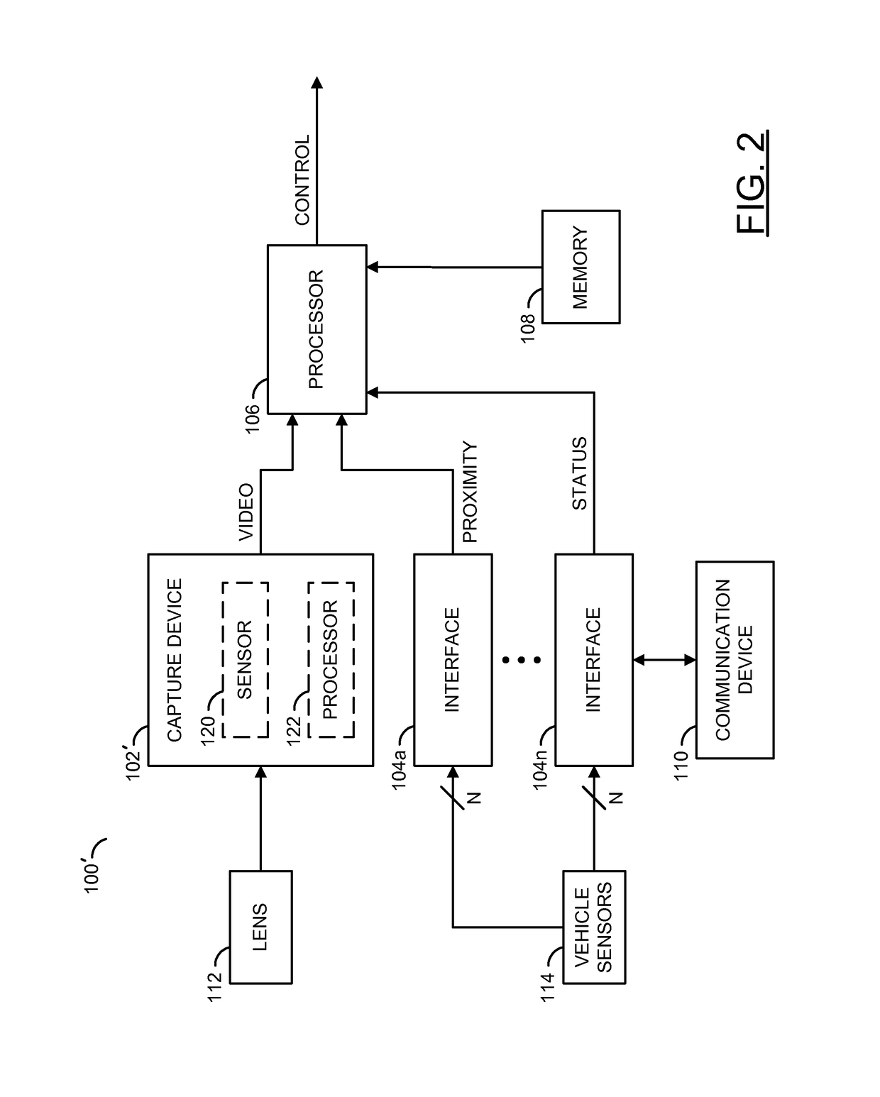
[0027]Referring to FIG. 4, an embodiment 200 illustrating determined fields of view and blind-spot detection is shown. An overhead (e.g., birds-eye-view) of the vehicle 50 is shown. Objects 52a-52n are shown around the vehicle 50. The objects 52a-52n may be nearby cars (or vehicles, or pedestrians, or structures, etc.).

[0028]The vehicle 50 is shown having mirrors 154a-154c. The mirror 154a may be a side view mirror on the driver side of the vehicle 50. The mirror 154b may be a rear view mirror of the vehicle 50. The mirror 154c may be a side view mirror on the passenger side of the vehicle 50. The number and / or types of the mirrors 154a-154c may be varied according to the design criteria of a particular implementation.

[0029]The vehicle 50 is shown having sensors 114a-114d. The sensors 114a-114d may be configured to detect nearby objects (e.g., proximity sensors). For example, the sensors 114a-114n may be implemented as radar devices and / or sonar devices. The sensors 114a-114n may be...


PUM


Abstract

An apparatus comprising a first sensor, an interface, a second sensor and a processor. The first sensor may be configured to generate a video signal based on a targeted view of a driver. The interface may be configured to receive status information about one or more components of a vehicle. The second sensor may be configured to detect an object within a predetermined radius of the second sensor. The processor may be configured to determine a field of view of the driver based on the status information. The processor may be configured to generate a control signal in response to a cross reference between (i) a field of view of the driver and (ii) the detected object. The control signal may be used to alert the driver if the detected object is not in the field of view of the driver.

Description

FIELD OF THE INVENTION[0001]The present invention relates to video capture devices generally and, more particularly, to a blind-spot monitoring using machine vision and precise field of view (FOV) information.BACKGROUND OF THE INVENTION[0002]Blind zones, or blind spots, in a vehicle are a leading cause of accidents between vehicles. Studies show that a majority of drivers do not know how to align mirrors correctly. Furthermore, when drivers use vehicles that are not their own, or use a shared vehicle, drivers often find the process of manual mirror adjustment of vehicle mirrors to be too bothersome for a single trip.[0003]Current blind-spot detection systems are expensive (since they typically use radar), and tend to warn the user about vehicles that are in certain pre-determined zones around the vehicle. The warning is provided regardless of whether the driver is actually able to see surrounding vehicles or not. A decision to alert the driver (or not) is based on an assumption abou...

Claims


Application Information

Patent Timeline
Patent Type & Authority Patents(United States)
IPC IPC(8): G06T7/20G06T7/00H04N7/18B60R1/08G06K9/00G06V10/147
CPCB60R1/081H04N7/183G06T7/004G06T7/20G06K9/00805B60R2300/301B60R2300/102B60R2300/202B60R2300/8026B60R2300/8093G06T2207/30261B60R1/00G06V40/19G06V20/58G06V10/147G06T7/11
Inventor PERTSEL, SHIMONFINK, ALEXANDER
Owner AMBARELLA INT LP
Why Eureka
Try Eureka