Eureka AIR delivers breakthrough ideas for toughest innovation challenges, trusted by R&D personnel around the world.

Object detection system and method for a motor vehicle

Active Publication Date: 2019-01-17
VALEO VISION SA
View PDF0 Cites 1 Cited by
  • Summary
  • Abstract
  • Description
  • Claims
  • Application Information

AI Technical Summary

Benefits of technology

This patent describes a detection system for motor vehicles that uses pixelated light beams to increase accuracy in identifying objects. The system is easy to install and can be integrated into existing equipment, such as headlights or cameras, without adding extra weight or complexity. The detection system leverages the geometrical properties of the vehicle and a calculation by triangulation to determine the location of objects. This technology benefits a range of applications, from improving safety on the road to assisting with autonomous driving.

Problems solved by technology

First of all, they require the addition of on-board hardware that burdens the vehicle.
In general, this burdensome hardware is situated on the roof of the vehicle, thereby possibly causing problems with aerodynamics along with aesthetic problems.
An error or a variation of a few nanoseconds may result in an evaluation error in the distance of the order of a metre, which is unacceptable in the context of motor vehicle safety.

Method used


Image

  • Object detection system and method for a motor vehicle
  • Object detection system and method for a motor vehicle
  • Object detection system and method for a motor vehicle

Examples


Embodiment Construction

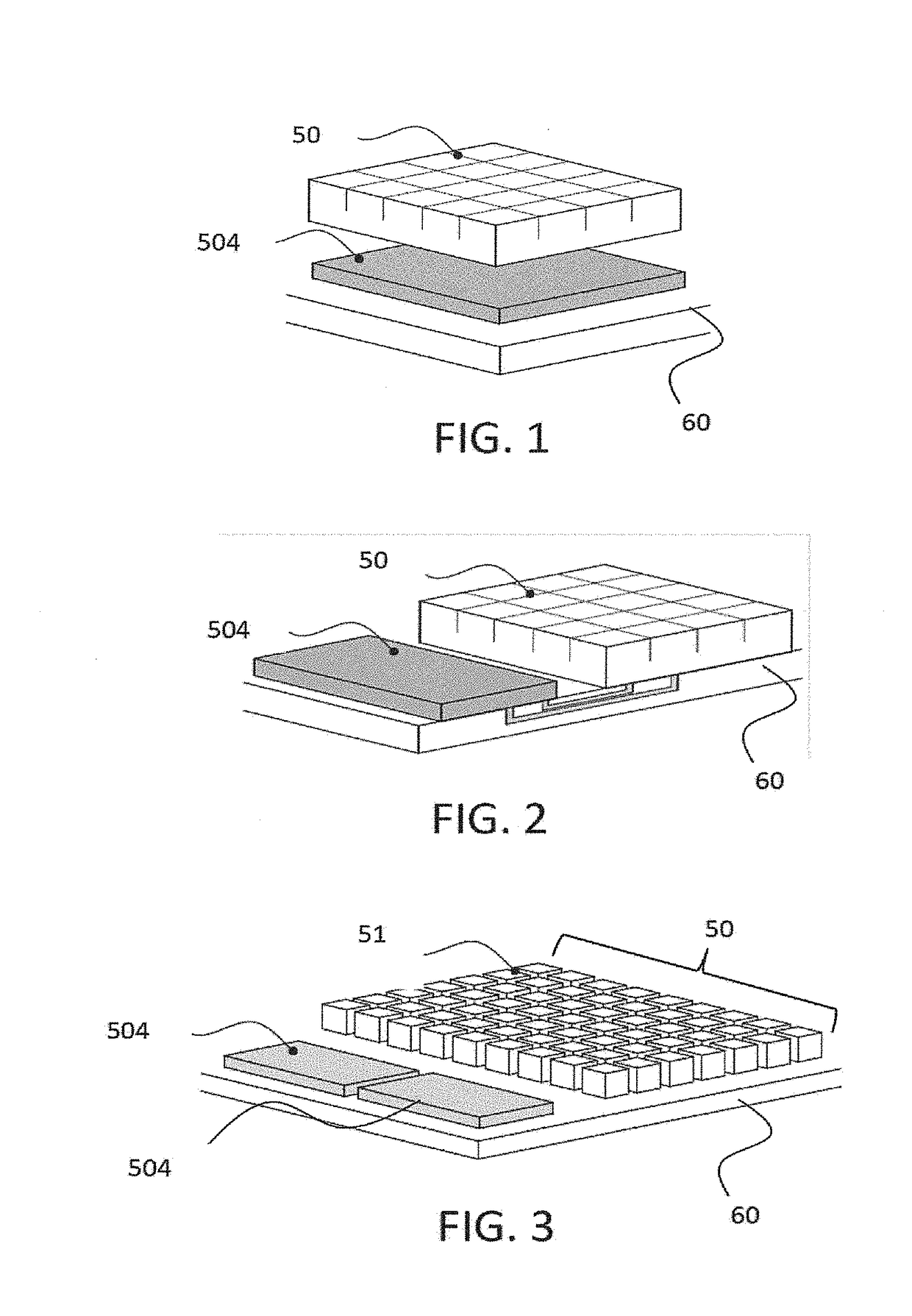
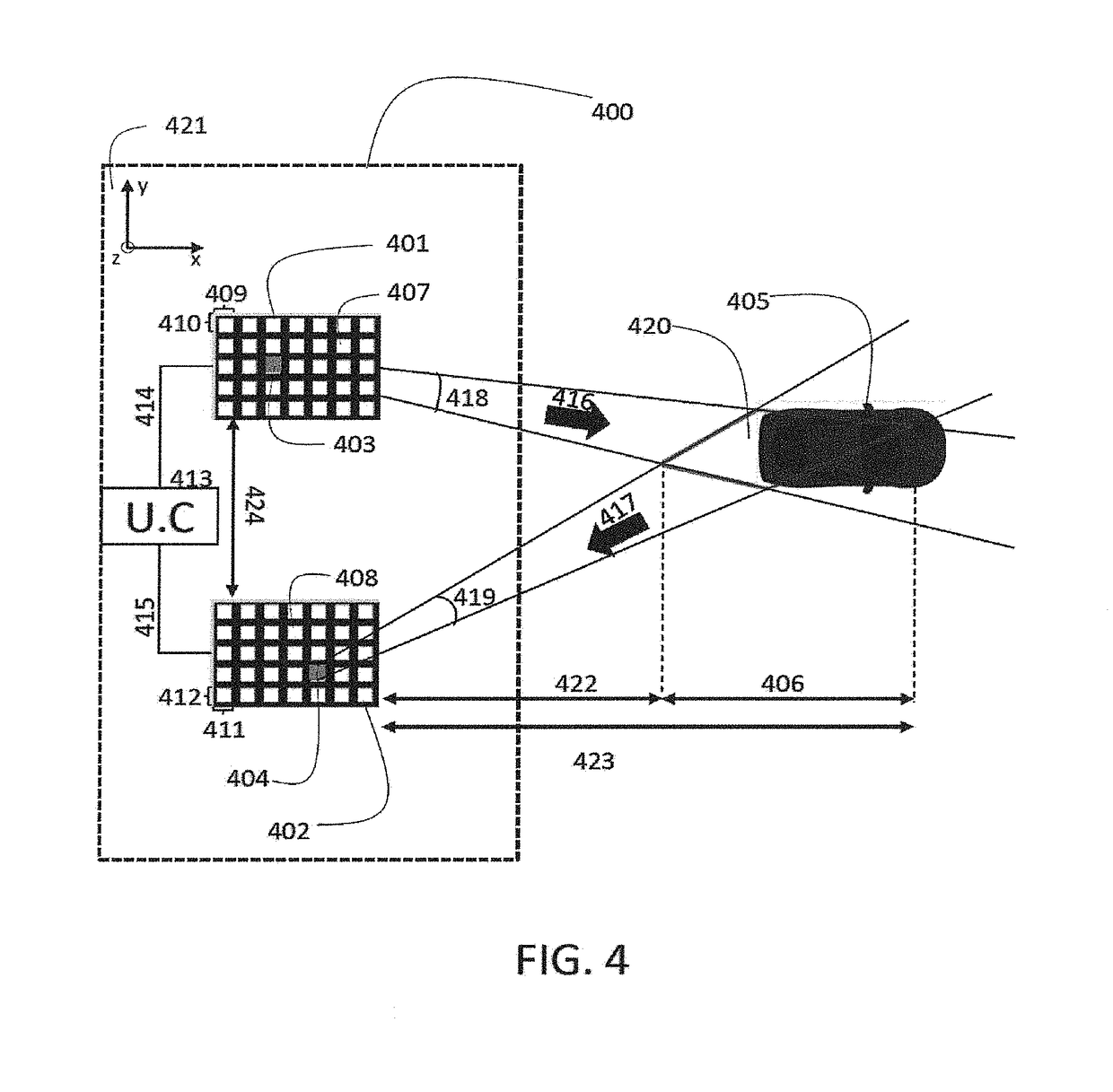
[0036]FIG. 4 illustrates an example of an object (405) detection system (400) according to the invention. This object detection system may be contained in a motor vehicle. For example, the detection system according to the invention may be integrated fully or partly into the lighting devices of the vehicle, in particular into the headlamps of the vehicle. Examples of integration of the object detection system according to the invention are described further on.

[0037]An object detection system 400 for a motor vehicle is a system that makes it possible to automatically ascertain the presence of one or more objects in the environment in which the vehicle is travelling. Automatically means that the user is not involved in the detection. The object detection system, when it is integrated into a vehicle, preferably makes it possible to detect objects that are situated on the path of the motor vehicle, and more generally objects that are situated in the scene of the vehicle. The scene of t...


PUM


Abstract

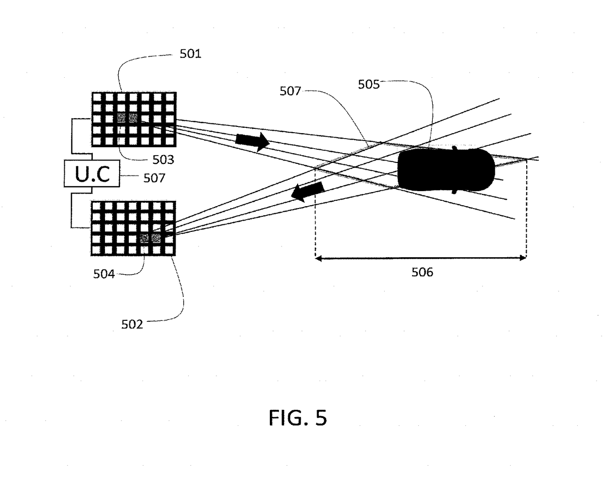
An object detection system for a motor vehicle is proposed. The system includes an array of electroluminescent light sources, an array of light sensors and a calculating unit. At least one of the electroluminescent light sources is able to emit a signal. At least one of the sensors is able to receive the emitted signal that has been reflected by an object. The calculating unit is able to calculate, by triangulation, the position of the object on the basis of the position, in one of the arrays of electroluminescent light sources, of at least one of the electroluminescent light sources able to emit a signal and on the basis of the position, in one of the arrays of light sensors, of at least one of the sensors able to receive the signal reflected by the object.

Description

FIELD OF THE INVENTION[0001]The present invention relates to the field of object detection systems and methods for motor vehicles.BACKGROUND[0002]Viewing the environment surrounding a motor vehicle is essential, in particular in the context of self-driving cars. It requires detecting and evaluating the distance from objects that are present on or near the road.[0003]The detection of objects that are present in the environment of a self-driving vehicle is nowadays mainly performed by lidars (acronym for light detection and ranging), or else by radars. These two systems make it possible to calculate the distance from an object situated near the vehicle. These systems send a wave, for example a laser beam or even a microwave beam, to an object that reflects said beam: the distance from the object is then deduced from the time that has elapsed between the moment when the wave was emitted and the moment when the wave reflected by the object was received.[0004]Radars and lidars, although ...

Claims


Application Information

Patent Timeline
IPC IPC(8): G01C3/10G01C3/08
CPCG01C3/08G01C3/10G01S17/48B60Q1/0023H01L25/167H01L27/156G01S17/931
Inventor DE LAMBERTERIE, ANTOINEMBATA, SAMIRACANONNE, THOMASTHIN, GUILLAUMELESAFFRE, OLIVIER-SEBASTIEN
Owner VALEO VISION SA
Why Eureka
Eureka Blog
Learn More