
System and method for monitoring change of intraocular pressure and contact lens for sensing change of intraocular pressure

a technology of intraocular pressure and monitoring system, which is applied in the field of monitoring technology for intraocular pressure, can solve the problems of inability to use contact tonometer as a long-term monitoring device of intraocular pressure, burden on eyes of users, and danger of blindness, so as to avoid damage or infection of the cornea and accurately measure the cornea

Active Publication Date: 2014-06-12
NAT TAIWAN UNIV
View PDF9 Cites 22 Cited by
  • Summary
  • Abstract
  • Description
  • Claims
  • Application Information

AI Technical Summary

Benefits of technology

This patent is about a system and method for monitoring changes in the pressure of a user's eyes through a contact lens. The system can accurately measure the cornea without using fluorescent agents, which could damage or infect the cornea. This helps to achieve long-term monitoring of intraocular pressure. The technical effects of this patent include improved accuracy and safety in monitoring intraocular pressure and potential damage to the cornea.

Problems solved by technology

However, frequent use of the contact tonometer for measurement causes a burden to eyes of a user, so the contact tonometer cannot be used as a device for long-term monitoring of an intraocular pressure.
For a patient with glaucoma, an excessive change of an instant intraocular pressure value brings about the danger of blindness.
However, in this measurement maimer, a professional person is required to assist in operating the instrument, and in the operation process, movement of the user head causes an error in the measurement result.
The reflective cornea curvature measurement manner has complex calculation and is limited to the weak reflected image.
Therefore, poor contrast of the reflected image increases an error value of the calculated curvature.
Additionally, this kind of measuring instrument is usually too large to carry, and therefore is unsuitable to be used as a device for monitoring an intraocular pressure.

Method used


Image

  • System and method for monitoring change of intraocular pressure and contact lens for sensing change of intraocular pressure
  • System and method for monitoring change of intraocular pressure and contact lens for sensing change of intraocular pressure
  • System and method for monitoring change of intraocular pressure and contact lens for sensing change of intraocular pressure

Examples


Embodiment Construction

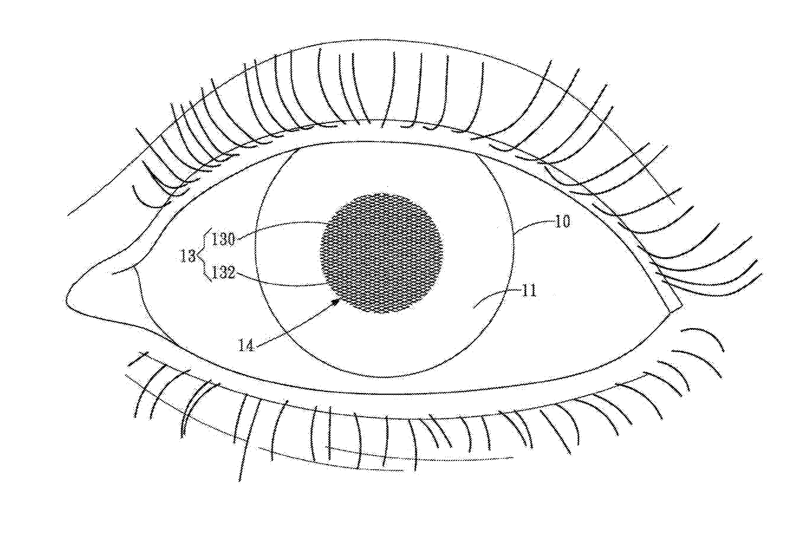
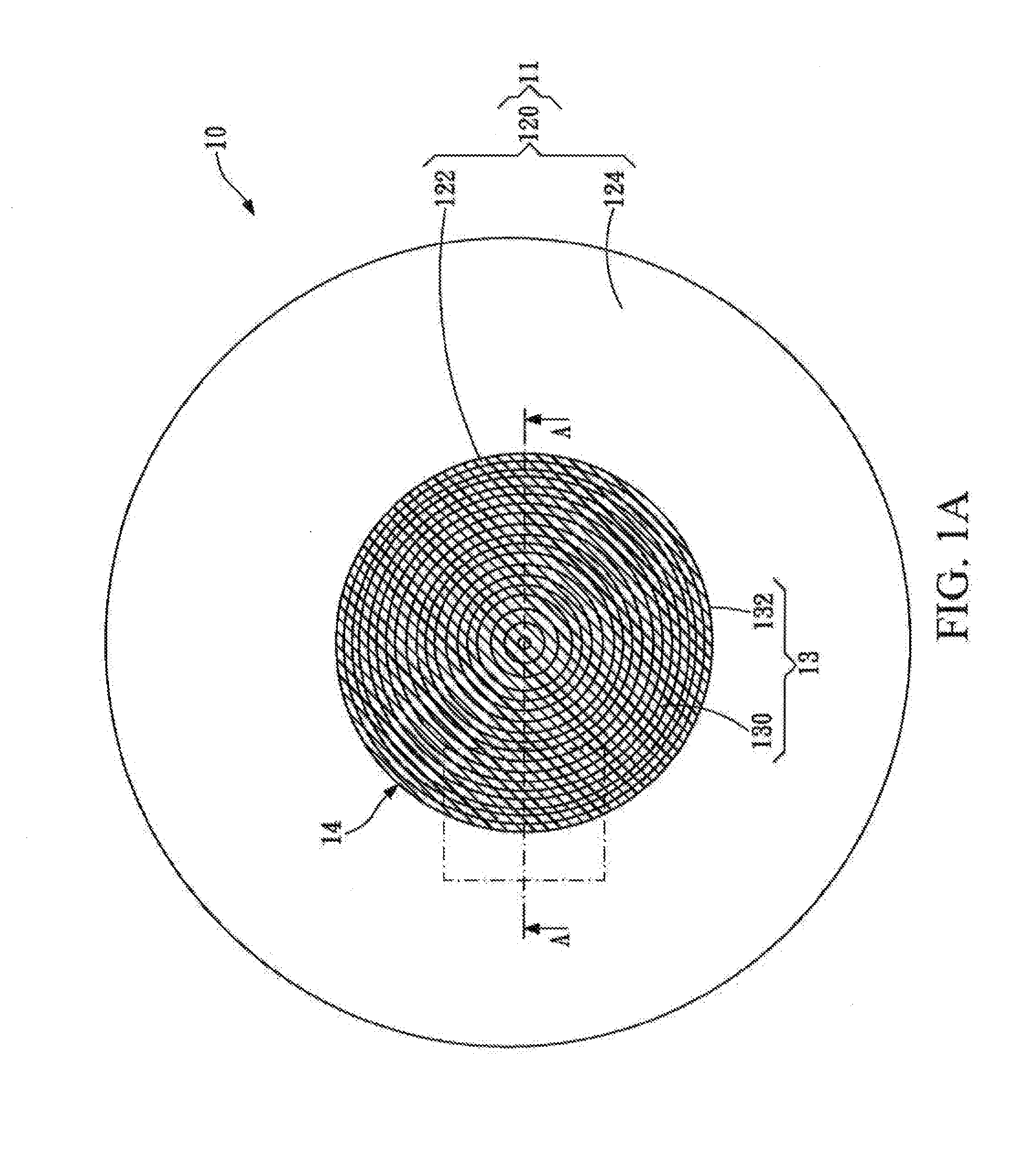
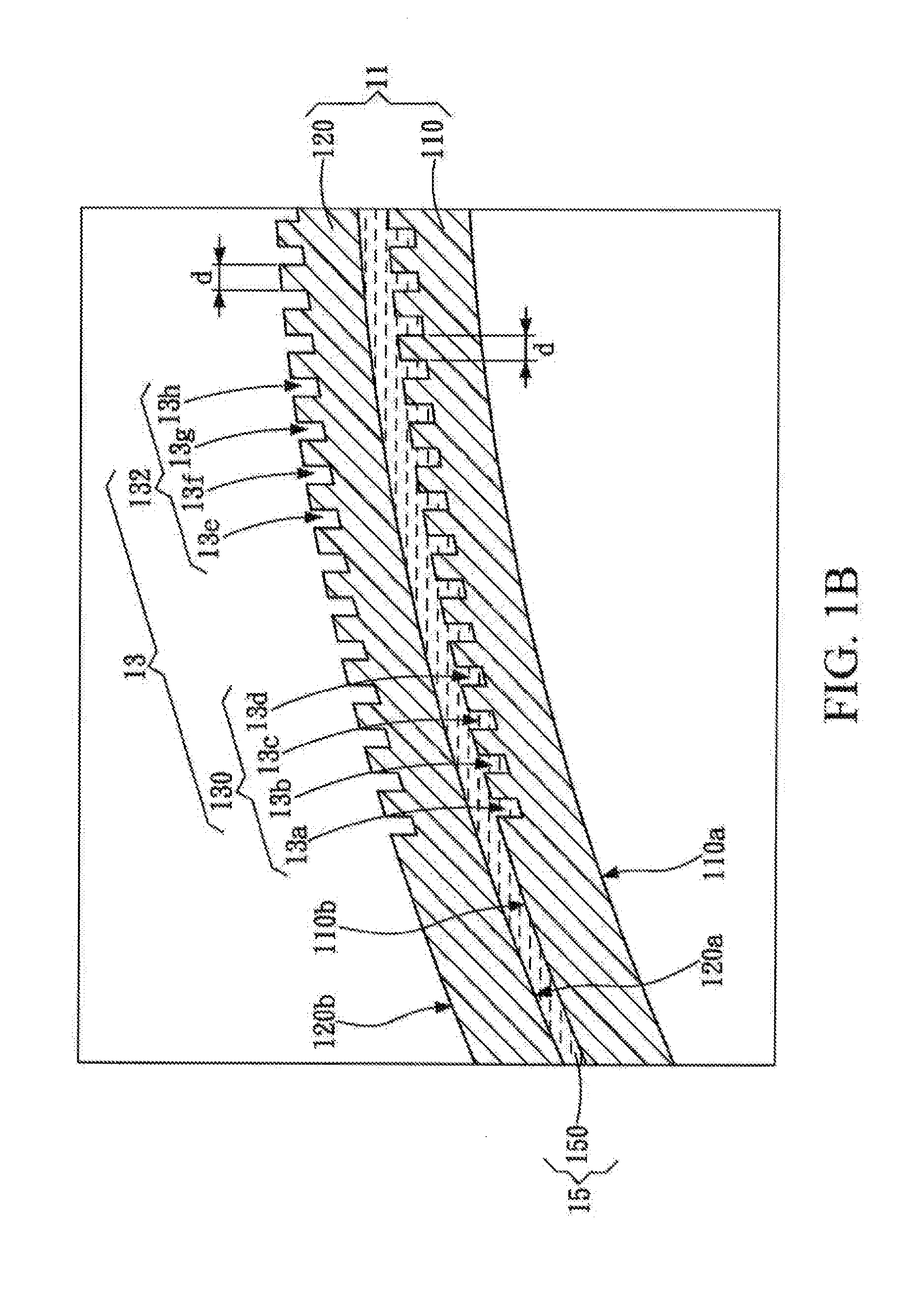
[0039]Please refer to FIG. 1A, FIG, 1B, FIG. 2A, FIG. 2B, FIG. 3A, FIG. 3B, FIG. 4A, FIG. 4B, FIG. 5A, and FIG. 5B, in which a contact lens 10 for sensing change of intraocular pressure includes a light transmissive material layer 11 (referred to as a first material layer 110 hereinafter), and a pattern 13 (referred to as a first pattern 130 hereinafter).

[0040]The first material layer 110 is divided into two regions, that is, an optical region 112 and a non-optical region 114. The optical region 112 is located in the center of the first material layer 110. The non-optical region 114 is located at the periphery of the optical region 112. The optical region 112 corresponds to a cornea region of an eyeball, and a region outside the optical region 112 of the first material layer 110 is the non-optical region 114. In other words, when a user wears the contact lens 10, the optical region 112 covers the cornea region of the eyeball of the user. In some embodiments, the non-optical region 1...


PUM


Abstract

A system and a method for monitoring change of intraocular pressure and a contact lens for sensing change of intraocular pressure are provided. The contact lens includes a first material layer and a first pattern. The center of the first material layer has an optical region, and the optical region corresponds to a cornea region of an eyeball. The first pattern is formed on the optical region. Furthermore, the contact lens may further include a second material layer and a second pattern. The second material layer is located on the first material layer. The second pattern is formed on the second material layer and overlaps with the first pattern to form a moire pattern.

Description

CROSS-REFERENCES TO RELATED APPLICATIONS[0001]This non-provisional application claims priority under 35 U.S.C. §119(a) on Patent Application No. 101147040 filed in Taiwan. R.O.C. on Dec. 12, 2012, the entire contents of which are hereby incorporated by reference.BACKGROUND OF THE INVENTION[0002]1. Technical Field[0003]The present invention relates to monitoring technology for an intraocular pressure (IOP), and in particular, to a system and a method for monitoring change of intraocular pressure and a contact lens for sensing an intraocular pressure change.[0004]2. Related Art[0005]An intraocular pressure of a human body is one of the standards for measuring glaucoma. An excessive change in the intraocular pressure causes damage to optic nerves, so if the change in the intraocular pressure can be observed and tracked, the occurrence opportunity of the glaucoma will be reduced.[0006]The most common manner for measuring an intraocular pressure is a contact applanation tonometer, for ex...

Claims


Application Information

Patent Timeline
Patent Type & Authority Applications(United States)
IPC IPC(8): A61B3/16
CPCA61B3/16A61B3/107
Inventor WANG, LONLIN, PIN-CHUNGWANG, I-JONG
Owner NAT TAIWAN UNIV
Learn More