Polishing device

a technology of polishing head and polishing head, which is applied in the direction of grinding head, grinding machine components, manufacturing tools, etc., can solve the problems of easy wear of the polishing head, easy collapse of the outer edge of the workpiece polished by the polishing head, and complicated polishing procedur

Inactive Publication Date: 2014-06-19
FU DING ELECTRONICSAL TECH JIASHAN +1
View PDF11 Cites 1 Cited by
  • Summary
  • Abstract
  • Description
  • Claims
  • Application Information

AI Technical Summary

Problems solved by technology

The polishing head may be deformed when positioned at a periphery of the workpiece, thus a peripheral edge of the workpiece polished by the polishing head may collapse.
However, when the pol

Method used


Image

  • Polishing device
  • Polishing device
  • Polishing device

Examples


Embodiment Construction

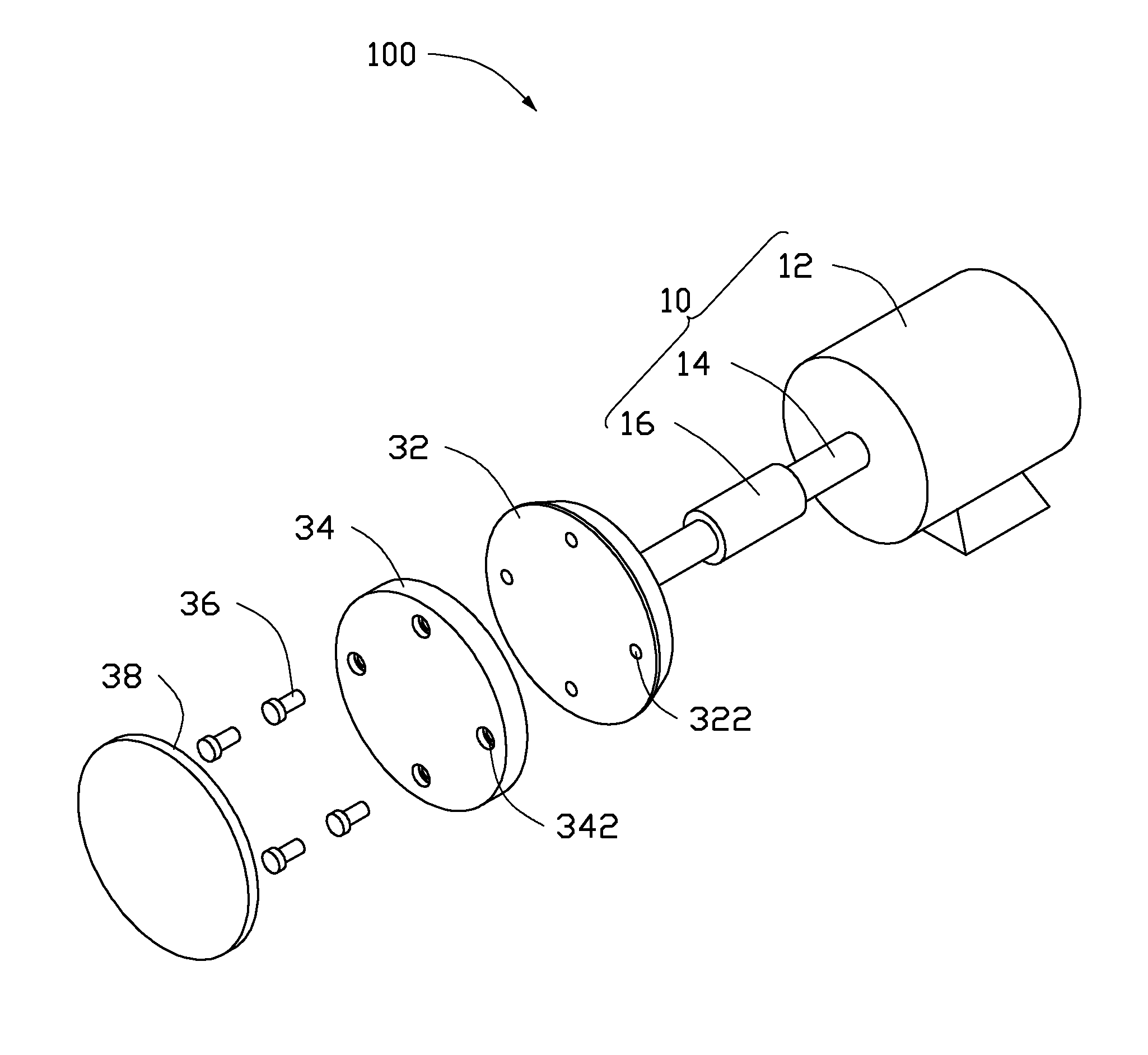
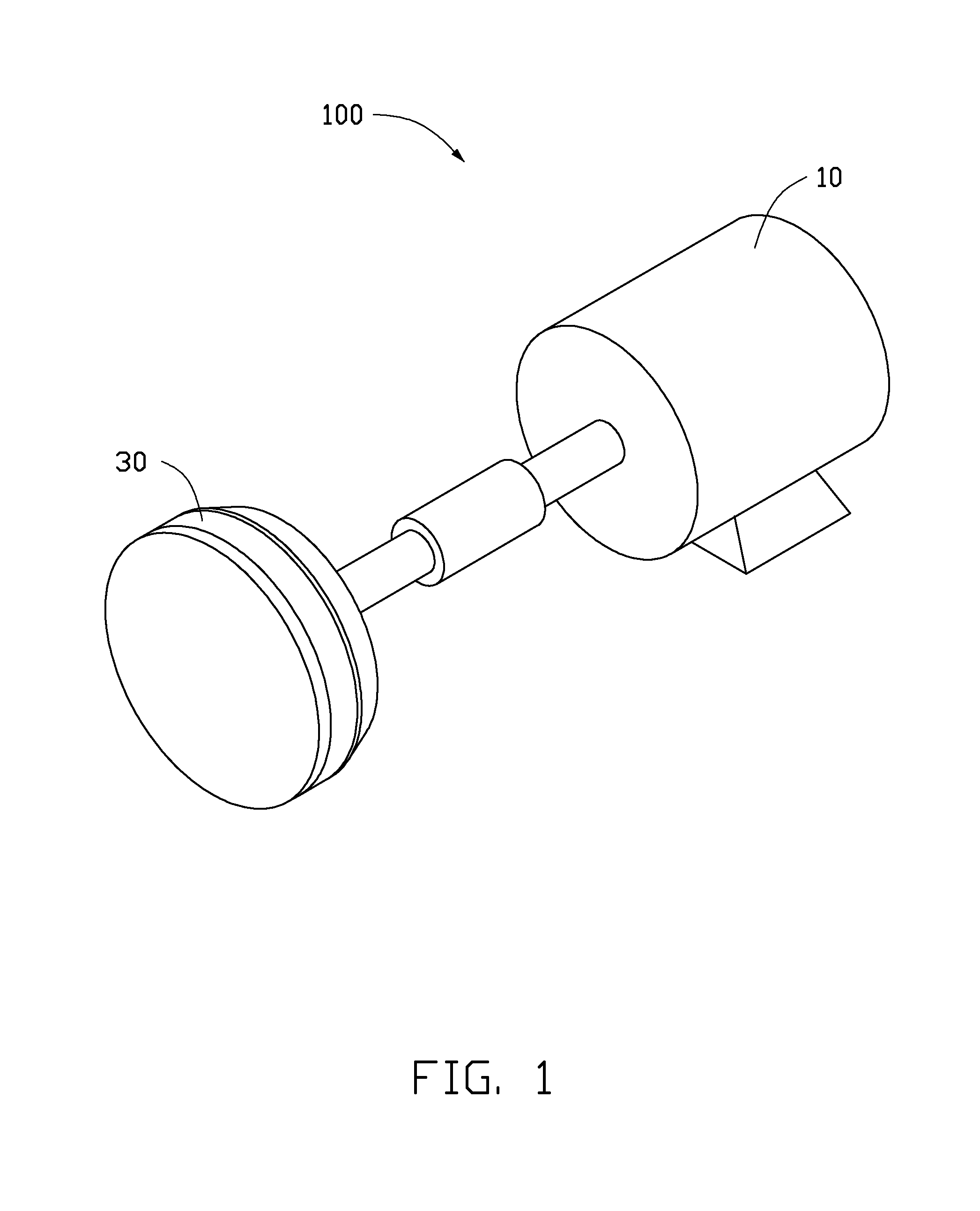
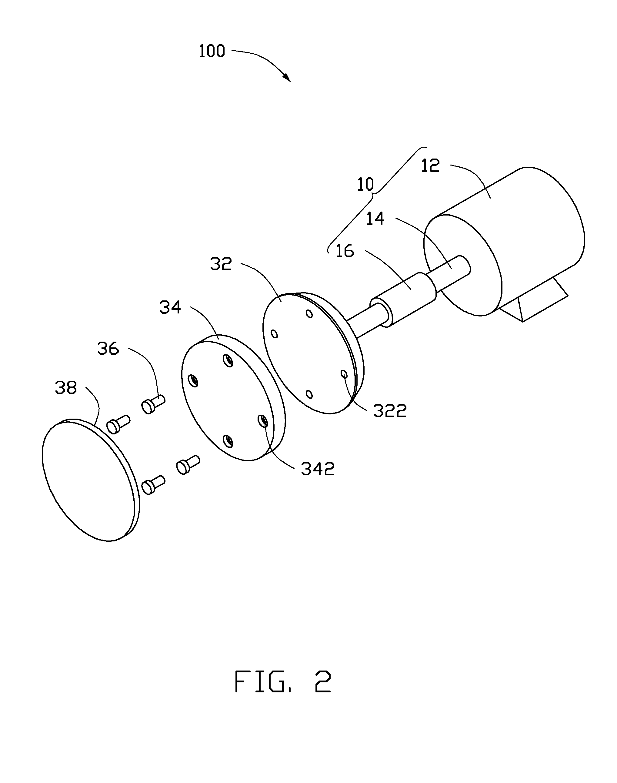
[0009]FIGS. 1 and 2 show an embodiment of a polishing device 100 employed to polish a housing of an electronic device, such as a desktop computer, a notebook, a tablet computer, or a mobile phone, thereby enhancing a finish of the housing. The polishing device 100 includes a driving member 10 and a polishing head 30 connected to the driving member 10. The polishing head 30 is driven by the driving member 10 to rotate and polish a surface of the housing.

[0010]The driving member 10 includes a driving body 12, an elastic coupler 16, and a rotating shaft 14 interconnecting the elastic coupler 16 and the driving body 12. The driving body 12 drives the elastic coupler 16 to rotate via the rotating shaft 14.

[0011]The polishing head 30 is substantially disc-shaped and is connected to the elastic coupler 16. The polishing head 30 includes a rotating body 32, a buffering pad 34, a plurality of fixing members 36, and an abrasive paper 38. In the embodiment, the rotating body 32 is made of meta...


PUM


Abstract

A polishing device includes a driving member and a polishing head. The polishing head is connected to the driving member and includes a rotating body made of metallic material, a buffering pad, and an abrasive paper. The buffering pad is made of plastic material and is fixedly assembled to the rotating body. The abrasive paper is fixed to a surface of the buffering pad opposite to the rotating body.

Description

BACKGROUND[0001]1. Technical Field[0002]The present disclosure relates to a polishing device.[0003]2. Description of Related Art[0004]Polishing devices may include a polishing head made of a plastic material to polish a workpiece. The polishing head may be deformed when positioned at a periphery of the workpiece, thus a peripheral edge of the workpiece polished by the polishing head may collapse. To protect the workpiece, a protecting fixture is employed to shield the edge of the workpiece. However, when the polishing device polishes the workpiece, it also polishes the protecting fixture. The polishing procedure is complicated using the protecting fixture, and the polishing head is worn down easily.[0005]Therefore, there is room for improvement in the art.BRIEF DESCRIPTION OF THE DRAWINGS[0006]The components in the drawings are not necessarily drawn to scale, the emphasis instead placed upon clearly illustrating the principles of the present disclosure. Moreover, in the drawings, li...

Claims


Application Information

Patent Timeline
IPC IPC(8): B24B41/00
CPCB24B29/00B24D9/08B24B41/002
Inventor YANG, MING-LUZHOU, TAO
Owner FU DING ELECTRONICSAL TECH JIASHAN
Why Eureka
Try Eureka