Multilayer wind spring for a display support and lifting support thereof

a multi-layer wind spring and display support technology, applied in the field of coil springs, can solve the problems of low efficiency and complicated oil application procedure, and achieve the effects of reducing the number of wind springs arranged, and reducing the number of wind springs

Active Publication Date: 2020-07-07
TAIZHOU STRONKIN ELECTRONICS
View PDF19 Cites 1 Cited by
  • Summary
  • Abstract
  • Description
  • Claims
  • Application Information

AI Technical Summary

Benefits of technology

[0008]An object of the present disclosure is to provide a multilayer wind spring for a display support, so as to solve the technical problem existing in the prior art that the multilayer wind spring has very short service life and the arching phenomenon of inner-layer metal sheet frequently occurs during its use, and to solve the problem that it is necessary to apply a lubricating oil between two adjacent elastic metal sheets and the oil application procedure is complicated with low efficiency.
[0009]Another object of the present disclosure is to provide a lifting support having the above-mentioned multilayer wind spring for a display support, which is ultra-thinner and has longer service life and lower maintenance cost compared with those in the prior art.

Problems solved by technology

An object of the present disclosure is to provide a multilayer wind spring for a display support, so as to solve the technical problem existing in the prior art that the multilayer wind spring has very short service life and the arching phenomenon of inner-layer metal sheet frequently occurs during its use, and to solve the problem that it is necessary to apply a lubricating oil between two adjacent elastic metal sheets and the oil application procedure is complicated with low efficiency.

Method used


Image

  • Multilayer wind spring for a display support and lifting support thereof
  • Multilayer wind spring for a display support and lifting support thereof
  • Multilayer wind spring for a display support and lifting support thereof

Examples


embodiment 1

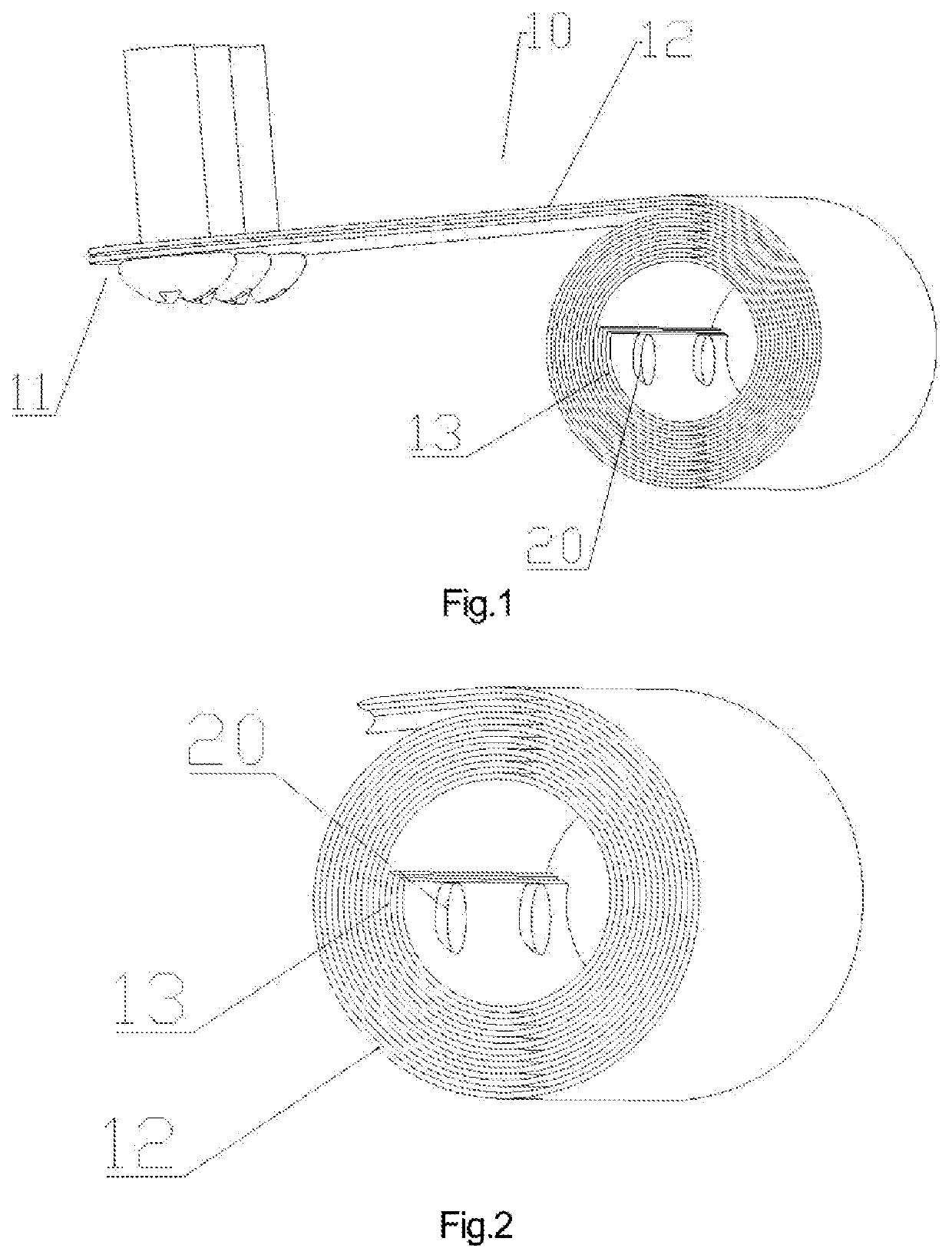
[0060]As shown in FIG. 1 and FIG. 2, the present embodiment provides a multilayer wind spring for a display support. The multilayer wind spring is formed by tightly attaching and winding a plurality of elastic metal sheets 10,

[0061]each of the elastic metal sheet 10 comprises: a stretching connection portion 11 which is not involved in winding and unwinding and is always kept in an initial state (the stretching connection portion 11 is an outwardly extending portion of an outermost layer or an outermost turn of the wound portion of the elastic metal sheet 10 after the multilayer wind spring is wound up to an extreme position), a movable sheet portion 12 which is involved in winding and unwinding, and an unmovable wound portion 13 which is not involved in stretching and is always kept in a wound state (the unmovable wound portion 13 is usually wound for not less than one turn, and for less than one turn in particular situations,

[0062]the stretching connection portion 11, the movable ...

embodiment 2

[0079]The structure of the present embodiment is basically the same as that of the first embodiment, except that:

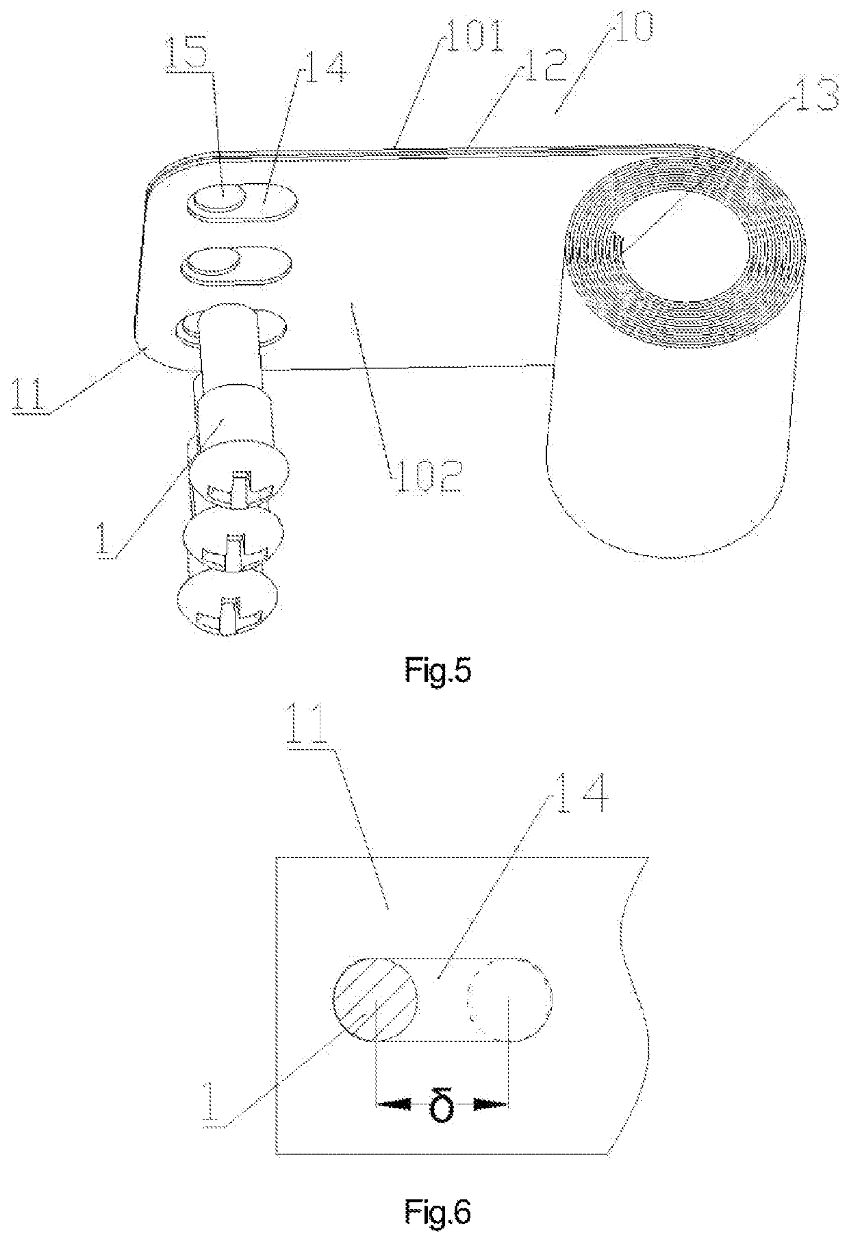
[0080]as shown in FIG. 5, the stretching connection portion 11 of the elastic metal sheet 10 is provided with a connection structure used for connection with a connected component,

[0081]the connection structure of some or all of the elastic metal sheets 10 (inner-layer elastic metal sheets 102 in the present embodiment) is a semi-restricted structure 14.

[0082]As shown in FIG. 6 and FIG. 7, the semi-restricted structure 14 is provided to have a movement allowance δ in an unwinding or winding-up direction of the elastic metal sheets 10, and

[0083]during an unwinding or winding process of the multilayer wind spring, the stretching connection portion 11 of the elastic metal sheet 10 provided with the semi-restricted structure 14 is arranged to be slidable within the range of the movement allowance δ relative to the connected component.

[0084]When in use, after the stretching co...

embodiment 3

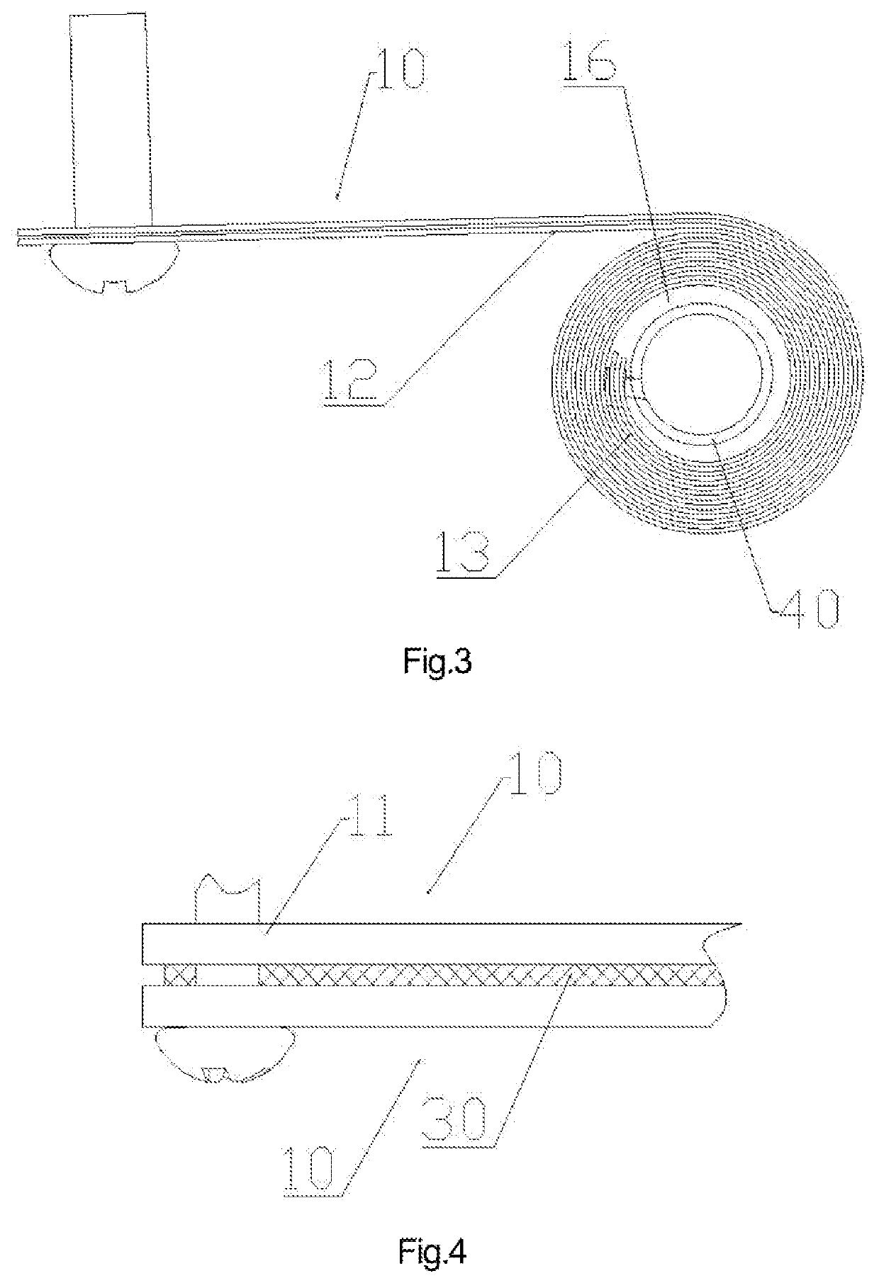
[0100]As shown in FIG. 1 and FIG. 9, the present embodiment discloses a lifting support having the above-mentioned multilayer wind spring, which comprises a stand column 2 and a lifting seat 3,

[0101]wherein, the lifting seat 3 is disposed on the stand column 2 in such a manner that it is slidable up and down,

[0102]the stretching connection portion 11 of the multilayer wind spring is connected to the lifting seat 3 or the stand column 2,

[0103]the stretching connection portion 11 of the elastic metal sheet 10 provided with the semi-restricted structure 14 is arranged to be slidable within the range of the movement allowance relative to the lifting seat 3 or the stand column 2,

[0104]the unmovable wound portion 13 of the multilayer wind spring is rotatably disposed on the stand column 2 or the lifting seat, and

[0105]the multilayer wind spring tends to force the lifting seat 3 to move upwards, thereby providing a supporting force for supporting the lifting seat 3.

[0106]The unmovable woun...


PUM


Abstract

A multilayer wind spring for a display support and a lifting support thereof, the multilayer wind spring is formed by tightly attaching and winding multiple elastic metal sheets, each of the elastic metal sheets comprises: a stretching connection portion which is not involved in winding and unwinding and is always kept in an initial state, a movable sheet portion which is involved in winding and unwinding, and an unmovable wound portion which is not involved in stretching and is always kept in a wound state, the stretching connection portion, the movable sheet portion, and the unmovable wound portion are formed integrally and sequentially arranged in an unwinding direction, and the elastic metal sheets of the unmovable wound portions are arranged fixedly relative to one another.

Description

CROSS-REFERENCE TO RELATED APPLICATIONS[0001]This application is a U.S. National Phase Application of International Application No. PCT / CN2017 / 100405, filed Sep. 4, 2017, which claims priority to Chinese Application No. 201710550795.7, filed Jul. 7, 2017, each of which are hereby incorporated by reference in their entirety.TECHNICAL FIELD[0002]The present disclosure relates to the technical field of coil spring, and in particular to a multilayer wind spring for a display support and a lifting support thereof.BACKGROUND ART[0003]At present, a display screen is usually supported by a lifting support, the lifting support comprises a stand column and a lifting seat, and the display screen is disposed on the stand column via the lifting seat with its height being adjustable.[0004]A constant force spring (a type of wind spring) is disposed between the stand column and the lifting seat, and arbitrary stopping of the display screen during the adjustment of its height can be achieved by mean...

Claims


Application Information

Patent Timeline
Patent Type & Authority Patents(United States)
IPC IPC(8): F16F1/10F16F1/12F16M11/24
CPCF16F1/10F16M11/24F16F1/123F16M2200/04F16M11/046F16M2200/047F16F3/06
Inventor XU, XIANGYUQU, BO
Owner TAIZHOU STRONKIN ELECTRONICS
Why Eureka
Try Eureka