
Apparatus for transversally sawing a tubular body

a tubular body and transversal sawing technology, applied in metal working apparatus, turning machine accessories, manufacturing tools, etc., can solve the problems of deteriorating sawing precision, difficult or substantially impossible to achieve, and inconvenient operation, etc., to achieve high sawing precision

Active Publication Date: 2014-06-26
GA VO MECCANICA SNC
View PDF14 Cites 8 Cited by
  • Summary
  • Abstract
  • Description
  • Claims
  • Application Information

AI Technical Summary

Benefits of technology

[0039]Advantageously, in the sawing station a means is provided for reversing the rotation speed of the tubular body during the sawing once the tubular body has rotated by a predetermined angle. This way, it is possible to obtain a very high sawing precision. In particular, this predetermined angle exceeds 360°, in particular is set between 380° and 390°.

Problems solved by technology

One cause for this longitudinal movement may be an imperfect alignment of the longitudinal rollers.
Even small longitudinal displacements from the working position may deteriorate the sawing precision, in particular the precision of the length of the sawn-away tubular portion that are obtained.
This condition is extremely difficult or substantially impossible to achieve by optimizing the construction of the existing equipment.

Method used


Image

  • Apparatus for transversally sawing a tubular body
  • Apparatus for transversally sawing a tubular body
  • Apparatus for transversally sawing a tubular body

Examples


Embodiment Construction

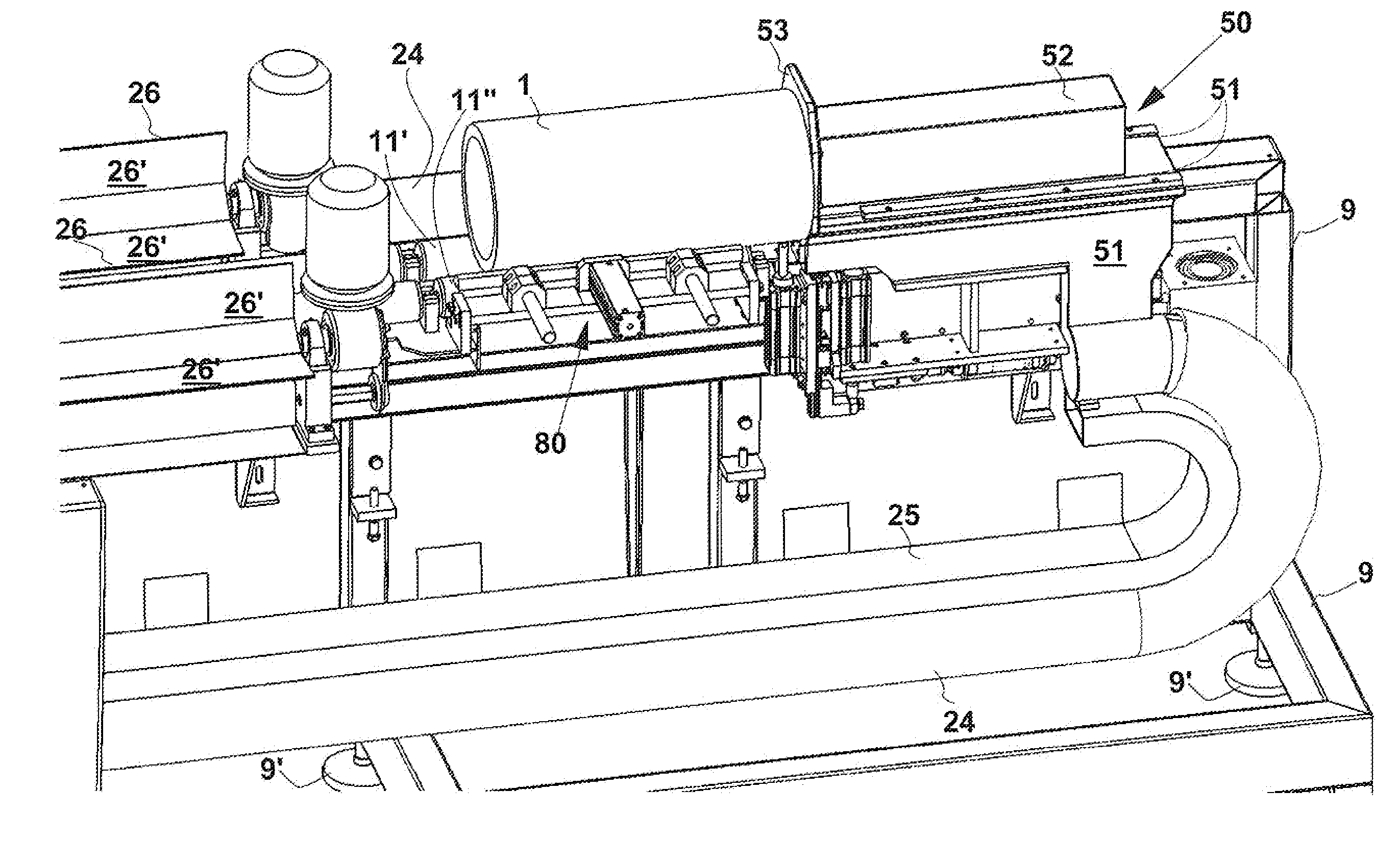
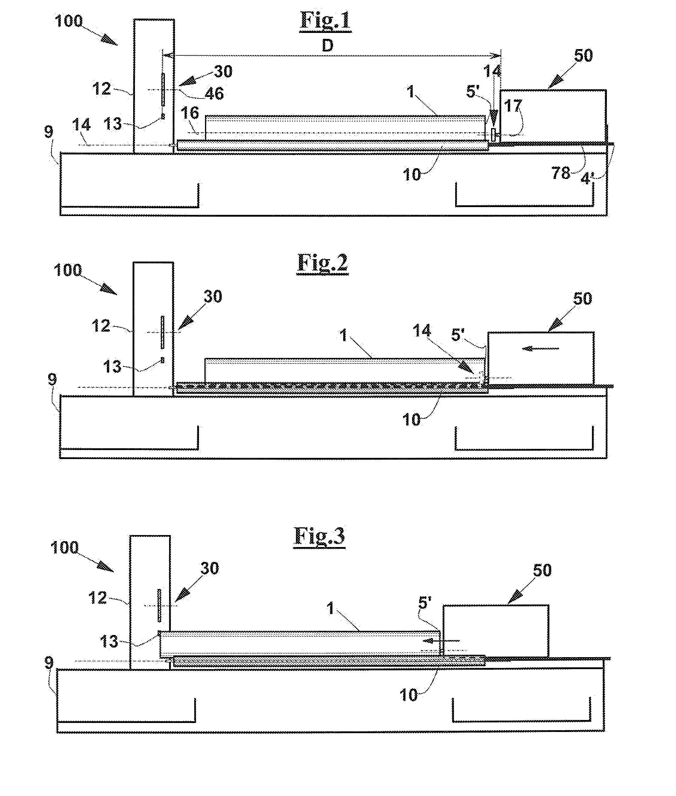
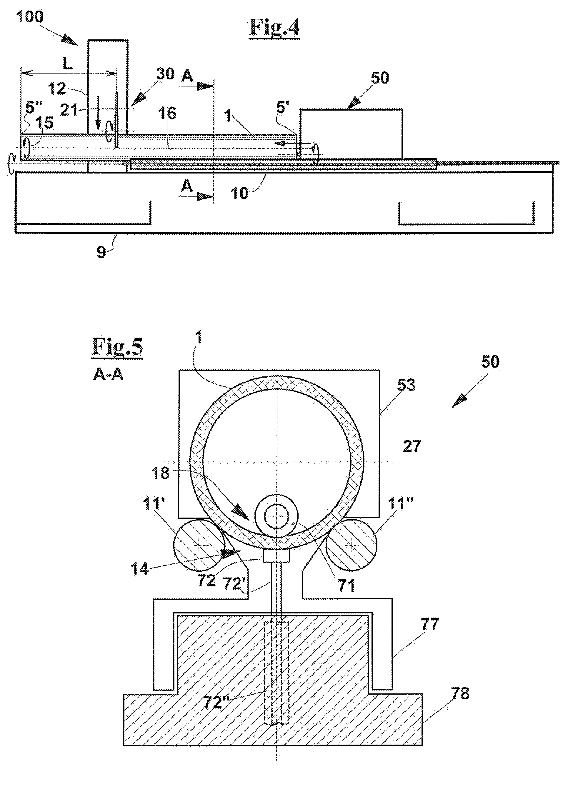
[0055]With reference to FIGS. 1 to 14, an apparatus 100 is described for transversally sawing a tubular body 1, for instance, for sawing cores to support a wound material. These bodies or tubular cores may be made of various materials, such as pressed cardboard or a plastic material like PVC.

[0056]Apparatus 100 comprises a frame 9 on which a support 12 is arranged for a sawing station 30. In particular, sawing station 30 comprises a chip-forming sawing device. For example, sawing station 30 comprises a circular saw or blade 35 that is rotatably arranged about an own axis 46, for carrying out a transverse sawing operation of tubular body 1 with formation of chips. In particular, sawing station 30 may be equipped and may work as described in IT1314837 or in WO2008 / 114115.

[0057]Below sawing station 30, a means 19′ may be provided for collecting sawn-away portions 1′ obtained by transversally sawing tubular body 1.

[0058]Apparatus 100 has a load means for loading tubular bodies to be saw...


PUM

PropertyMeasurementUnit
angleaaaaaaaaaa
angleaaaaaaaaaa
angleaaaaaaaaaa

Abstract

Technical problem: a low sawing precision of tubular bodies of an apparatus comprising a transverse sawing station (30), in particular said apparatus equipped with a chip-forming saw means (35), a support (11′,11″) arranged to maintain the tubular bodies (1) in rotation during the sawing step, and also comprising a carriage means (50) for carrying the tubular body (1) along the direction of its own longitudinal axis (16) towards the sawing station (30), in particular preserving the possibility of removing chips produced during the sawing from the inside of the tubular body (1), such low sawing precision, in terms of length and smoothness of the end of the portions depending upon possible small longitudinal translation movements of the tubular body (1) along the support (11′,11″).
Solution: providing a carriage means (50) that comprises a holding means (14) for longitudinally holding the tubular body (1), the holding means (14) comprising a rotatable element (71) arranged to relatively rollingly engage with a surface portion (18) of the tubular body (1), in particular the rotatable element (71) is arranged to engage by rolling and pressing onto an inner surface portion (18) of said tubular body (1) proximate to said first end (5′) and radially corresponding to a surface portion of the tubular body (1) to contact a counter-support element (72) and radially corresponding to a surface portion of said tubular body (1) that is in contact with a counter-support element (72) (FIG. 18)

Description

FIELD OF THE INVENTION[0001]The present invention relates to an apparatus for transversally sawing tubular bodies, for example tubular cores for supporting coils of wound material.DESCRIPTION OF THE TECHNICAL PROBLEM[0002]Apparatuses are known for transversally sawing tubular bodies made of such materials as pressed cardboard or plastics, which are well suited for serving as cores for supporting coils of tape material, for example. These apparatuses are normally equipped with a transverse chip-forming saw device, in particular they are equipped with circular rotating blades.[0003]In order to obtain a maximum sawing precision, as well as smoother and more regular end portions of the sawn tubular bodies, a device is normally provided for bringing into rotation the tubular bodies about their own axis while performing a sawing operation by the blade.[0004]Examples of such apparatuses can be found, for instance, in IT1314837 and in WO2008 / 114115.[0005]These apparatuses comprise a cradle ...

Claims


Application Information

Patent Timeline
Patent Type & Authority Applications(United States)
IPC IPC(8): B26D3/16B26D7/06B26D7/18
CPCB26D3/16B26D3/164B26D7/02B26D2007/0018B26D7/0616B26D7/1863B26D7/06Y10T82/16098Y10T82/16426Y10T82/16655Y10T82/16967
Inventor TANCREDI, ANTONIOBENVENUTI, STEFANO
Owner GA VO MECCANICA SNC
Learn More