
Sawing gearbox

A gear box and sawing technology, applied in metal sawing equipment, belts/chains/gears, sawing machines, etc., can solve the problems of reduced saw blade cutting efficiency and cutting accuracy, reduced gear service life, and unstable gear transmission. , to achieve the effect of small vibration, protection of the output shaft, and improvement of sawing accuracy

Inactive Publication Date: 2014-02-26
东莞市晋诚机械有限公司
View PDF5 Cites 3 Cited by
  • Summary
  • Abstract
  • Description
  • Claims
  • Application Information

AI Technical Summary

Problems solved by technology

[0002] At present, there is a gap between the gears in the design and manufacture of the gears in the gear box of the sawing machine. In the subsequent use, the teeth will be deformed with the increase of the use time, so that the gap between the gears will increase, resulting in a gap between the gears. The transmission between them is unstable, the cutting efficiency and cutting accuracy of the saw blade are reduced, and the service life of the gear is reduced
[0003] At present, the motor in the gear box of the saw machine used for heavy-duty cutting is directly connected to the output shaft, so that the ability of the saw blade to cut metal depends entirely on the power of the motor, and the requirements for the motor are very high, which greatly increases the cost. The saw blade needs a lot of torque. When the cutting is stopped, the saw blade cannot stop immediately due to the large inertia, and the output bearing bears all the force.

Method used


Image

  • Sawing gearbox
  • Sawing gearbox
  • Sawing gearbox

Examples


Embodiment Construction

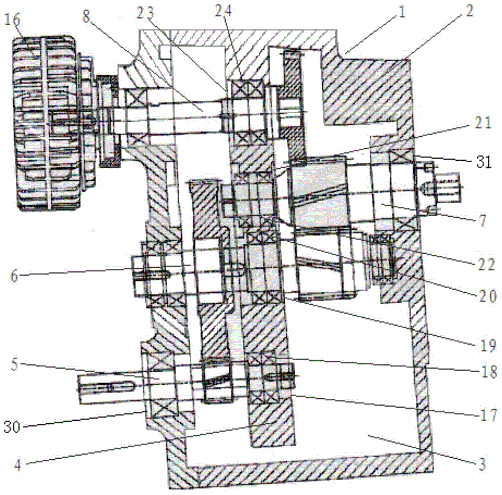
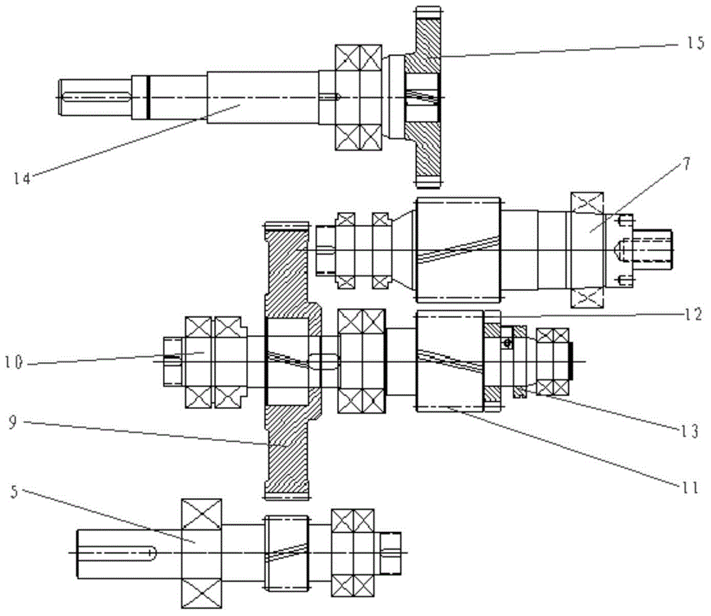
[0027] Such as Figure 1-3 As shown, the sawing gear box according to Embodiment 1 of the present invention includes a box body 2, a working chamber 3 for gear work is provided inside the box body 2, and a fixing plate 4 is provided in the middle of the working chamber 3 , the bottom of the fixed plate 4 is provided with a functional hole 17 for the input gear shaft 5 to pass through, the functional hole 17 is provided with a bearing 18 that matches the input gear shaft 5, and the functional hole 17 The position corresponding to the intermediate gear shaft 10 above is provided with a functional hole 2 19 for the intermediate gear shaft 10 to pass through. The functional hole 2 19 is provided with a bearing 20 matching with the intermediate gear shaft 10. The functional hole 2 19 The position corresponding to the output gear shaft 7 is provided with a functional hole 3 21 for the output gear shaft 7 to pass through. The functional hole 3 21 is provided with a bearing 3 22 that ...


PUM


Abstract

The invention relates to a sawing gearbox. The sawing gearbox comprises a box body, wherein a working cavity is arranged inside the box body, an input hole used for fixing an input gear shaft is formed in the left end face of the box body, an output hole used for fixing an output gear shaft is formed in the right end face of the box body, the input gear shaft is arranged on the lower portion of the box body, a speed reducer is arranged above the input gear shaft, the output gear shaft is arranged above the speed reducer, and a brake device is arranged above the output gear shaft. The sawing gearbox has the advantages that the sawing accuracy is improved, cost is reduced greatly, the sawing gearbox is applicable to heavy cutting due to the adoption of a spiral gear transmission structure, the accuracy is stable, and the sawing gearbox is reliable, durable, high in overload bearing capacity, low in energy consumption, small in vibration and low in noise.

Description

technical field [0001] The invention relates to the field of sawing machines, in particular to a sawing gear box for heavy cutting. Background technique [0002] At present, there is a gap between the gears in the design and manufacture of the gears in the gear box of the sawing machine. In the subsequent use, the teeth will be deformed with the increase of the use time, so that the gap between the gears will increase, resulting in a gap between the gears. The transmission between them is unstable, the cutting efficiency and cutting accuracy of the saw blade are reduced, and the service life of the gear is reduced. [0003] At present, the motor in the gear box of the saw machine used for heavy-duty cutting is directly connected to the output shaft, so that the ability of the saw blade to cut metal depends entirely on the power of the motor, and the requirements for the motor are very high, which greatly increases the cost. The saw blade needs a lot of torque. When the cutt...

Claims


Application Information

Patent Timeline
Patent Type & Authority Applications(China)
IPC IPC(8): F16H57/023F16H57/12
CPCB23Q5/10B23D47/123B23Q5/20B23Q5/56F16H57/023F16H57/028F16H57/12
Inventor 谢永福王南艳
Owner 东莞市晋诚机械有限公司
Learn More