Hand-held battery powered center punch band clamp tool

a battery-powered, center-type technology, applied in the direction of bundling articles, bundling machine details, other domestic articles, etc., can solve the problems of requiring the user to exert tremendous force to both tighten and secure the bands, the connection is subject to failure, and the use of manual banding tools is known

Inactive Publication Date: 2014-06-26
ROOTH CRAIG J
View PDF8 Cites 3 Cited by
  • Summary
  • Abstract
  • Description
  • Claims
  • Application Information

AI Technical Summary

Benefits of technology

[0011]The present invention overcomes the limitations and disadvantages present in the art by providing a battery operated, hand-held banding tool having a center punch for use in tightening and securing center punch band clamps. A power operated band clamp tensioning tool in accordance with the present invention preferably comprises driving tool having a hand-held main body containing a motor and electrical power source configured for rotationally driving a chuck, and a band tensioner connected to the main body and mechanically coupled to the chuck. The band tensioner preferably includes a gear box, and a gear box mount which functions to secure the gear box to the main body in coupled relation with the chuck. In a preferred embodiment, the gear box mount includes a generally U-shaped rigid strap which engages the rear of the hand-held main body to secure the gear box. The gear box contains a worm gear axially coupled to the chuck for powered driven rotation thereby. The worm gear is in intermeshing relation with a winder gear disposed within the gear box and configured for rotation about an axis disposed generally perpendicular to the worm gear axis. A winder, defining a band-receiving slot, is affixed to the winder gear and rotationally driven thereby. A cover plate is attached to the gear box in covering relation with the gears, and defines an aperture through which the winder projects. A punch assembly, defining a band-receiving slot, is connected to the distal end of the cover plate with the slot disposed in forwardly spaced aligned relation with the winder. The punch assembly includes a pivotal punch that functions to allow the user to lock a center punch band clamp by deforming the band within the confines of the band buckle upon impact. The punch preferably includes a first end pivotally connected to the cover plate, and a second end having a first side adapted with a generally pointed tip and an opposing, generally planar second side that provides a surface for receiving an impact blow from a hammer or other blunt striking implement so as to securely lock the band clamp. The present invention thus provides an improved power operated banding tool that allows for powered tightening of a center punch band clamp, and locking of the band using an integral hammer punch.

Problems solved by technology

The device disclosed by Jansen, however, is manually operated and thus requires the user to exert tremendous force to both tighten and secure the band.
Accordingly, the connection is subject to failure should the user be unable to apply sufficient force.
Further, the use of a manual banding tool has been known to tier and fatigue the user, particularly, after repeated use.
As a result of the disadvantages present with manual banding tools, at least one manufacturer has developed a battery powered banding tool.
The Hayata device, however, has been designed for use with a variety of band clamps, and thus is burdened by significant limitations when employed for use with center punch band clamps.
One such limitation associated with the Hayata device, is its failure to provide any structure for securing the band clamp once tightened.

Method used


Image

  • Hand-held battery powered center punch band clamp tool
  • Hand-held battery powered center punch band clamp tool
  • Hand-held battery powered center punch band clamp tool

Examples


Embodiment Construction

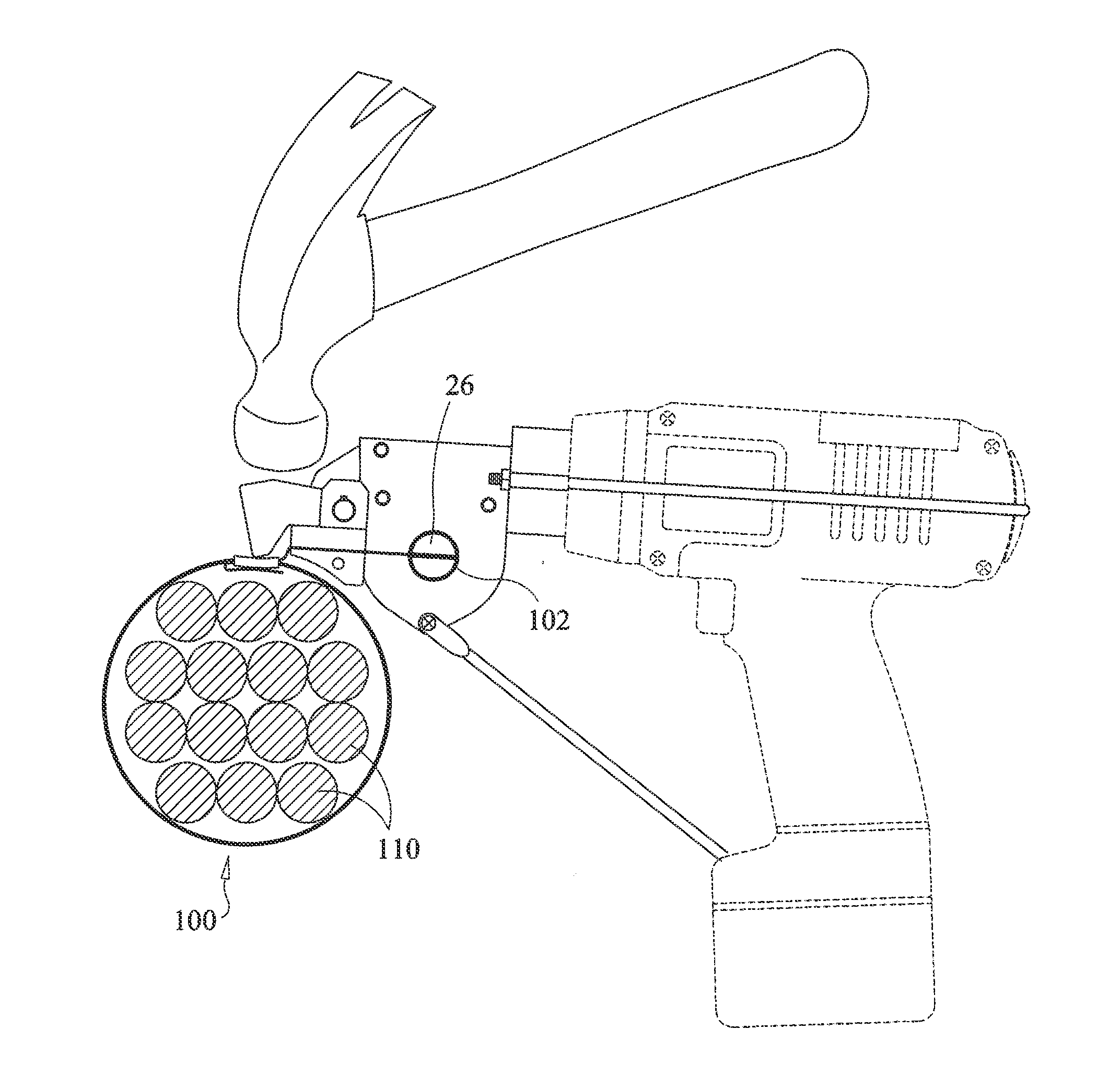
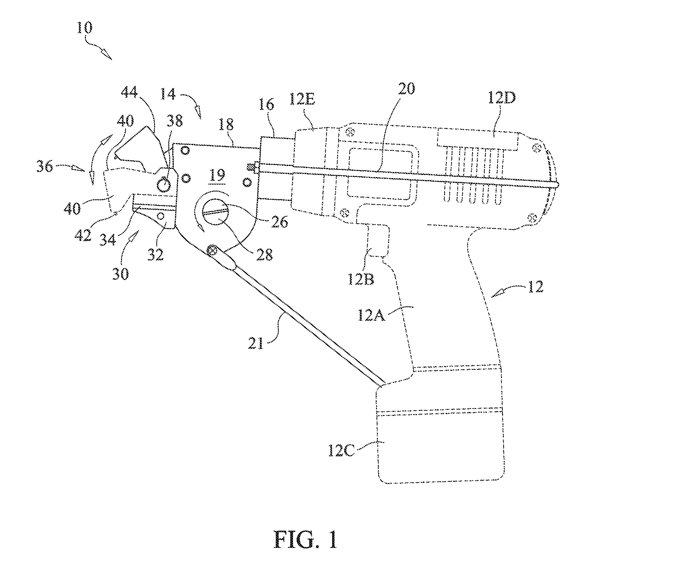
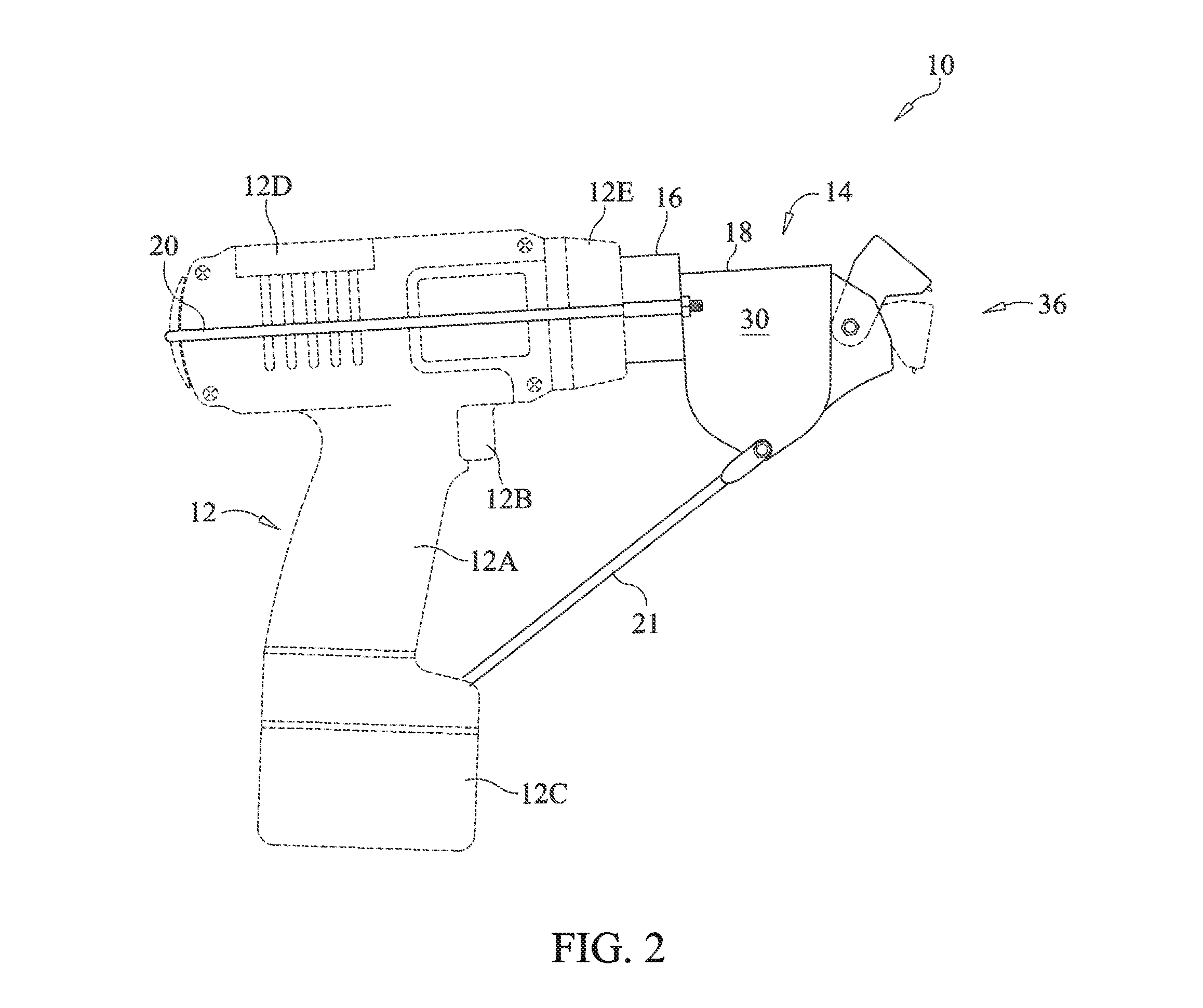
[0023]With reference now to the drawings, FIGS. 1-6 depict a power operated banding tool, generally referenced as 10, specifically adapted with an integral center punch for use in tightening and securing center punch band-type clamps in accordance with the present invention.

[0024]A power operated banding tool in accordance with the present invention preferably comprises a hand-held electrically powered driving tool, such as a drill, having a main body 12 including grip 12A having a trigger-type actuator 12B, a battery power source 12C, a proximal or rear end 12D, and a distal or front end 12E containing a rotatable chuck. As is known in the power tool art, the driving tool may comprise a battery powered, cordless electric drill having an internal electric motor and mechanical linkages configured for rotationally driving a chuck at the distal end 12E of main body 12.

[0025]As illustrated in FIGS. 1 and 2, a band tensioner, generally referenced as 14, is attached to the distal end 12E ...


PUM

PropertyMeasurementUnit
tensionaaaaaaaaaa
electrical poweraaaaaaaaaa
forceaaaaaaaaaa

Abstract

A battery powered banding tool is adapted with a punch for use in tightening and securing center punch type band clamps. A hand-held electrically powered drill is configured for rotationally driving a band tensioner mounted thereto. The band tensioner includes a gear box, and a mount including a generally U-shaped rigid strap which engages the rear of the driving tool to secure the gear box. The gear box contains a worm gear axially coupled to the chuck for powered driven rotation thereby. The worm gear is in intermeshing relation with a winder gear disposed within the gear box and configured for rotation about an axis disposed generally perpendicular to the worm gear axis. A winder, defining a band-receiving slot, is affixed to the winder gear and rotationally driven thereby. A punch assembly, defining a band-receiving slot, is disposed in forwardly spaced aligned relation with the winder. The punch assembly includes a pivotal punch that functions to allow the user to lock a center punch band clamp by deforming the band within the confines of the band buckle upon impact.

Description

CROSS REFERENCE TO RELATED APPLICATIONS[0001]This application is a Continuation-In-Part of U.S. patent application Ser. No. 13 / 222,537, filed on Aug. 31, 2011.STATEMENT REGARDING FEDERALLY SPONSORED RESEARCH OR DEVELOPMENT[0002]N / ACOPYRIGHT NOTICE[0003]A portion of the disclosure of this patent document contains material that is subject to copyright protection. The copyright owner has no objection to the facsimile reproduction by anyone of the patent document or patent disclosure as it appears in the Patent and Trademark Office patent file or records, but otherwise reserves all copyrights rights whatsoever.BACKGROUND OF THE INVENTION[0004]1. Field of the Invention[0005]The present invention relates to tools for use with band-type clamps used for applying radial compression to one or more objects, and more particularly to a hand-held battery-powered banding tool having a center punch for use in tightening and securing center punch band clamps.[0006]2. Description of Related Art[0007]...

Claims


Application Information

Patent Timeline
Patent Type & Authority Applications(United States)
IPC IPC(8): B65B13/34
CPCB65B13/345B65B13/22B65B13/24B65B13/30B65B13/305
Inventor ROOTH, CRAIG J.
Owner ROOTH CRAIG J
Why Eureka
Try Eureka