Antenna and method for manufacturing antenna

a technology of antenna and manufacturing method, which is applied in the direction of antenna supports/mountings, radiating element structural forms, and catheter structures, etc. it can solve the problems of complex human body and device positions, buckling and instability of the antenna layer, and the inconvenient support of the portion between the antenna layer and the ground layer, etc., to achieve the effect of controlling the radiation efficiency of the antenna

Inactive Publication Date: 2014-06-26
SAMSUNG ELECTRONICS CO LTD
View PDF8 Cites 6 Cited by
  • Summary
  • Abstract
  • Description
  • Claims
  • Application Information

AI Technical Summary

Benefits of technology

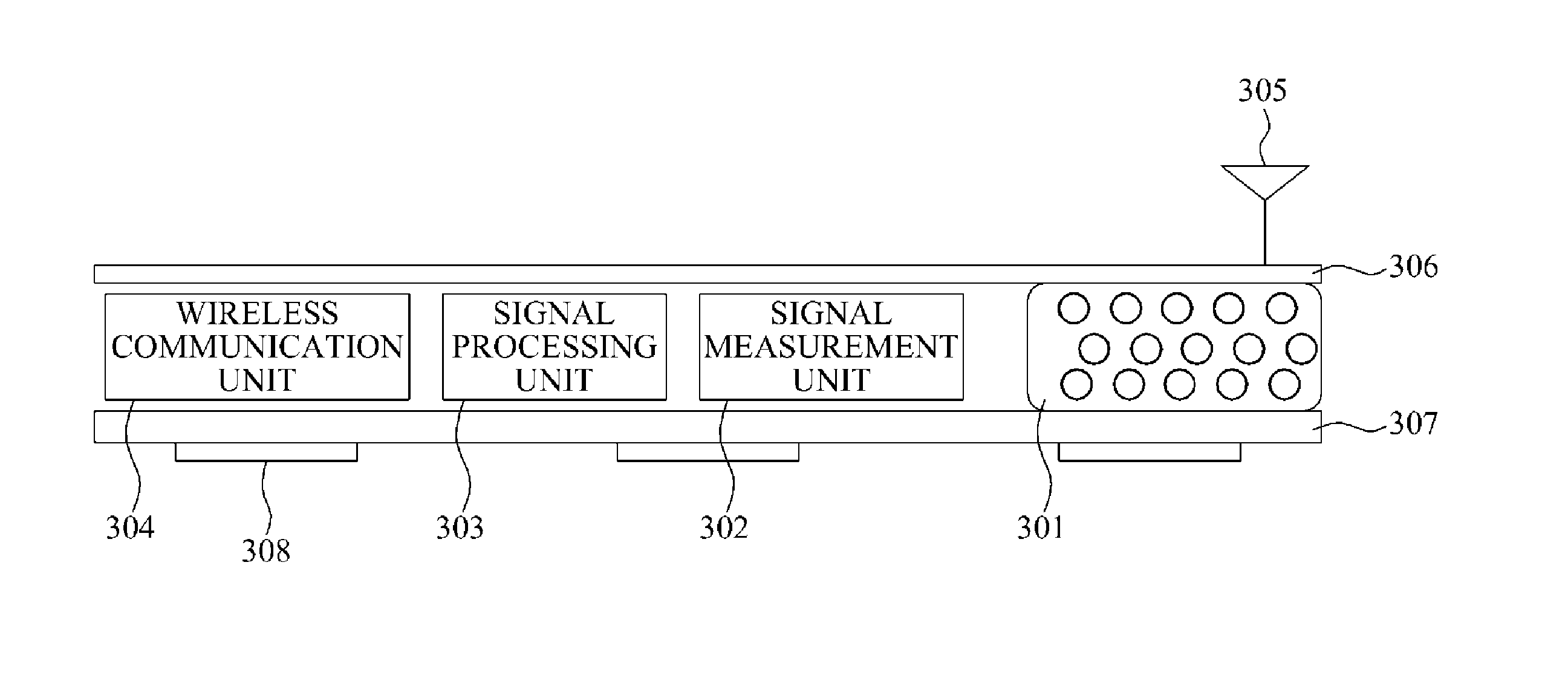
[0015]A surface area or a thickness of the air layer may control radiation efficiency of the antenna.

Problems solved by technology

However, due to the air layer being filled with air, the antenna does not conveniently support the portion between the antenna layer and the ground layer.
Thus, buckling and instability can occur in the antenna layer subject to compression and tensile load.
Therefore, various factors including characteristics of a medium of the human body and positions of the device need to be complexly considered.

Method used


Image

  • Antenna and method for manufacturing antenna
  • Antenna and method for manufacturing antenna
  • Antenna and method for manufacturing antenna

Examples


Embodiment Construction

[0037]The following detailed description is provided to assist the reader in gaining a comprehensive understanding of the methods, apparatuses, and / or systems described herein. However, various changes, modifications, and equivalents of the systems, apparatuses and / or methods described herein will be apparent to one of ordinary skill in the art. Also, descriptions of functions and constructions that are well known to one of ordinary skill in the art may be omitted for increased clarity and conciseness.

[0038]Throughout the drawings and the detailed description, the same reference numerals refer to the same elements. The drawings may not be to scale, and the relative size, proportions, and depiction of elements in the drawings may be exaggerated for clarity, illustration, and convenience.

[0039]The features described herein may be embodied in different forms, and are not to be construed as being limited to the examples described herein. Rather, the examples described herein have been p...


PUM

PropertyMeasurementUnit
dielectric constantaaaaaaaaaa
geometric shapeaaaaaaaaaa
strengthaaaaaaaaaa

Abstract

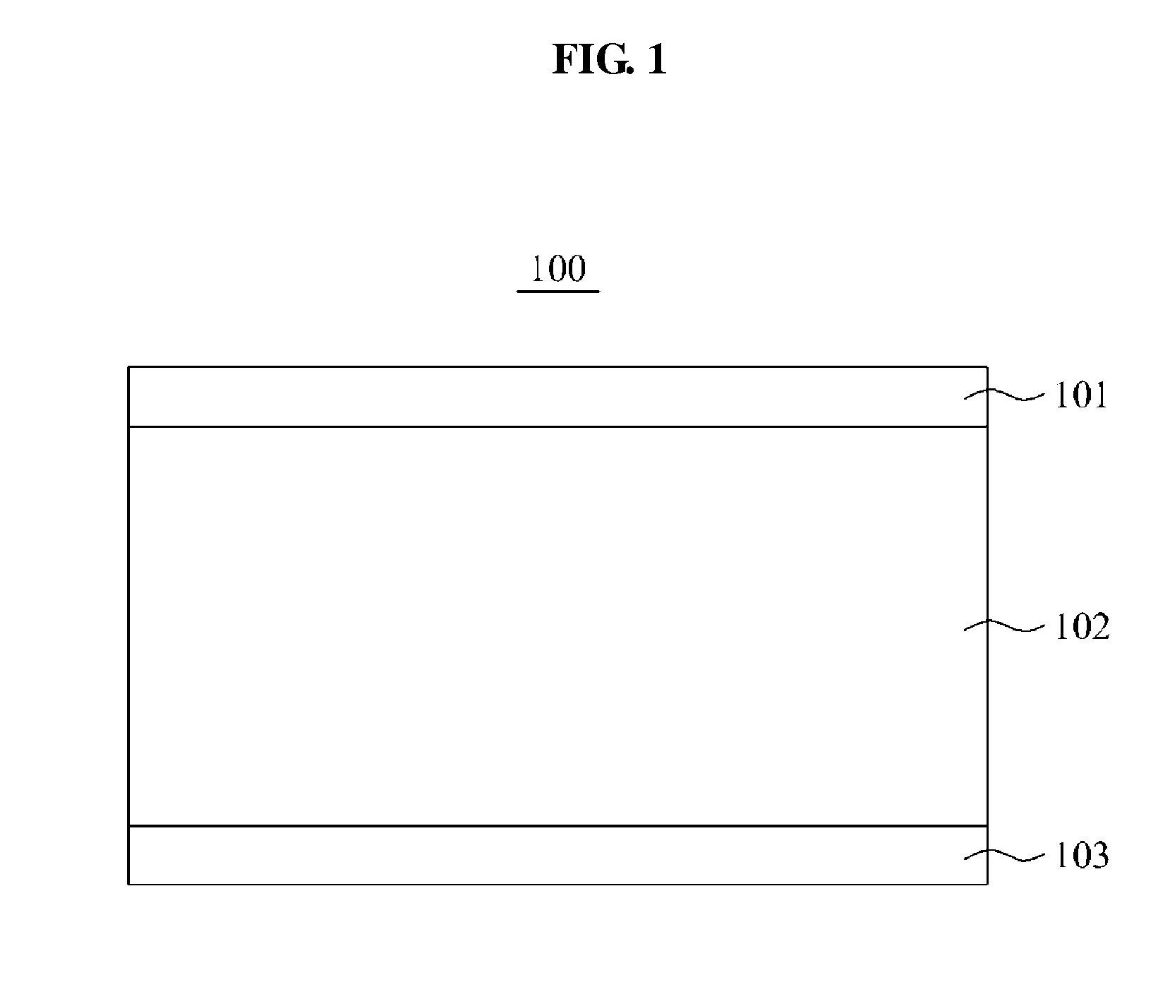
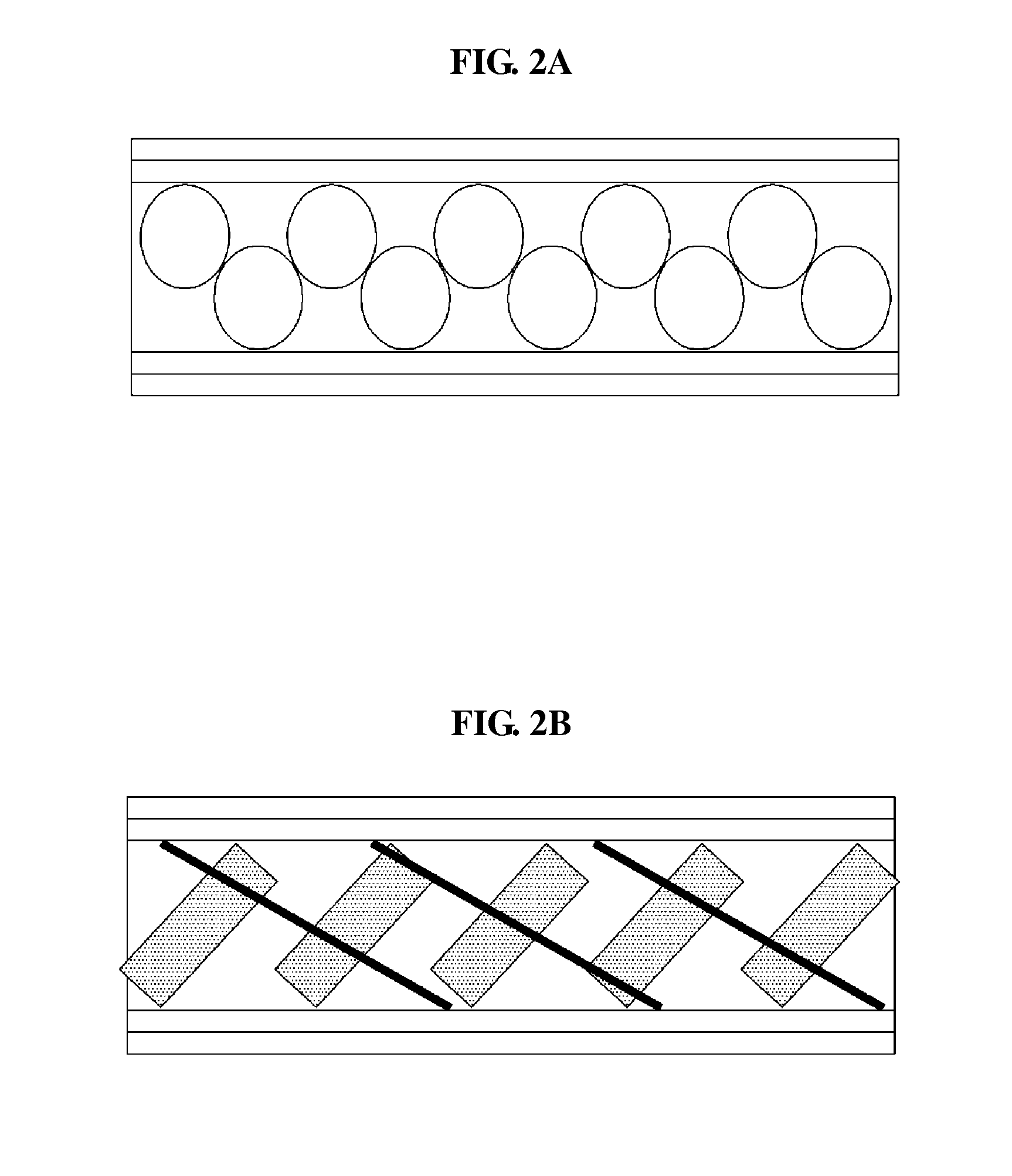
An antenna and a method of manufacturing the antenna are provided. The antenna may include an antenna surface, a ground plane, and an air layer comprising a porous structure.

Description

CROSS-REFERENCE TO RELATED APPLICATION(S)[0001]This application claims the benefit under 35 USC §119(a) of Korean Patent Application No. 10-2012-0150397, filed on Dec. 21, 2012, in the Korean Intellectual Property Office, the entire disclosure of which is incorporated herein by reference for all purposes.BACKGROUND[0002]1. Field[0003]The following description relates to an antenna and a method for manufacturing the antenna. For example, the antenna is an antenna supported using an air layer that is stably structured.[0004]2. Description of Related Art[0005]A physiological signal measured from a body of a user may continuously be monitored throughout a patient's daily routine for diagnosis of diseases or management of a user's activity. A sensor is typically attached to the skin of the user to monitor the physiological signal of the user. Such a sensor may monitor electrocardiogram (ECG), electromyogram (EMG), electroencephalogram (EEG), galvanic skin response (GSR), electrooculogram...

Claims


Application Information

Patent Timeline
Patent Type & Authority Applications(United States)
IPC IPC(8): H01Q1/38B29C44/00B29C67/20
CPCH01Q1/38B29C67/202B29C67/20B29C44/00C08J9/26C08J9/30C08J2201/0462C08J2207/10C08J2383/04H01Q1/273A61B5/02H01Q1/24
Inventor KO, BYUNG HOONPARK, SANG YUNKIM, YOUN HOHONG, YOUNG JUNPARK, KUN KOOKSHIN, KUN SOO
Owner SAMSUNG ELECTRONICS CO LTD
Why Eureka
Try Eureka