Bonding device

Inactive Publication Date: 2014-07-03
FU DING ELECTRONICSAL TECH JIASHAN +1
View PDF11 Cites 12 Cited by
  • Summary
  • Abstract
  • Description
  • Claims
  • Application Information

AI Technical Summary

Benefits of technology

The patent text describes a method of bonding electronic components by manually coating adhesive onto one workpiece and then sticking it to another workpiece. This process is time-consuming, requires a lot of labor, and has low accuracy. The technical effect of this patent is to provide a more efficient and accurate method for bonding electronic components.

Problems solved by technology

However, manually bonding of the workpieces wastes a large amount of labor and time, and the corresponding cost is high.
In addition, a bonding accuracy of the workpieces is relatively low.

Method used


Image

  • Bonding device
  • Bonding device
  • Bonding device

Examples


Embodiment Construction

[0013]The disclosure is illustrated by way of example and not by way of limitation in the figures of the accompanying drawings in which like references indicate similar elements. It should be noted that references to “an” or “one” embodiment in this disclosure are not necessarily to the same embodiment, and such references mean “at least one.”

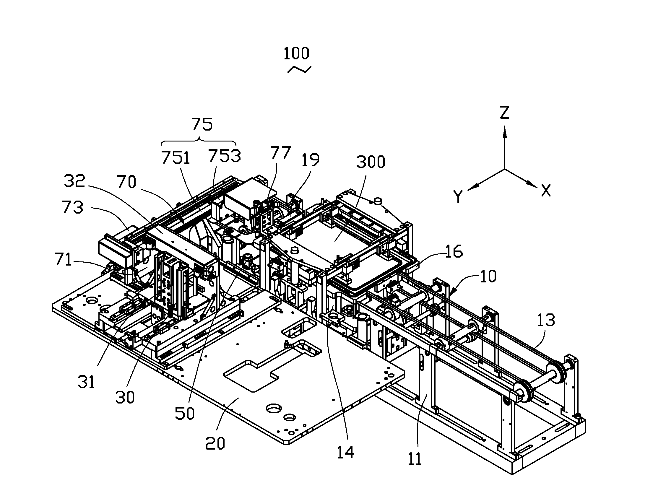
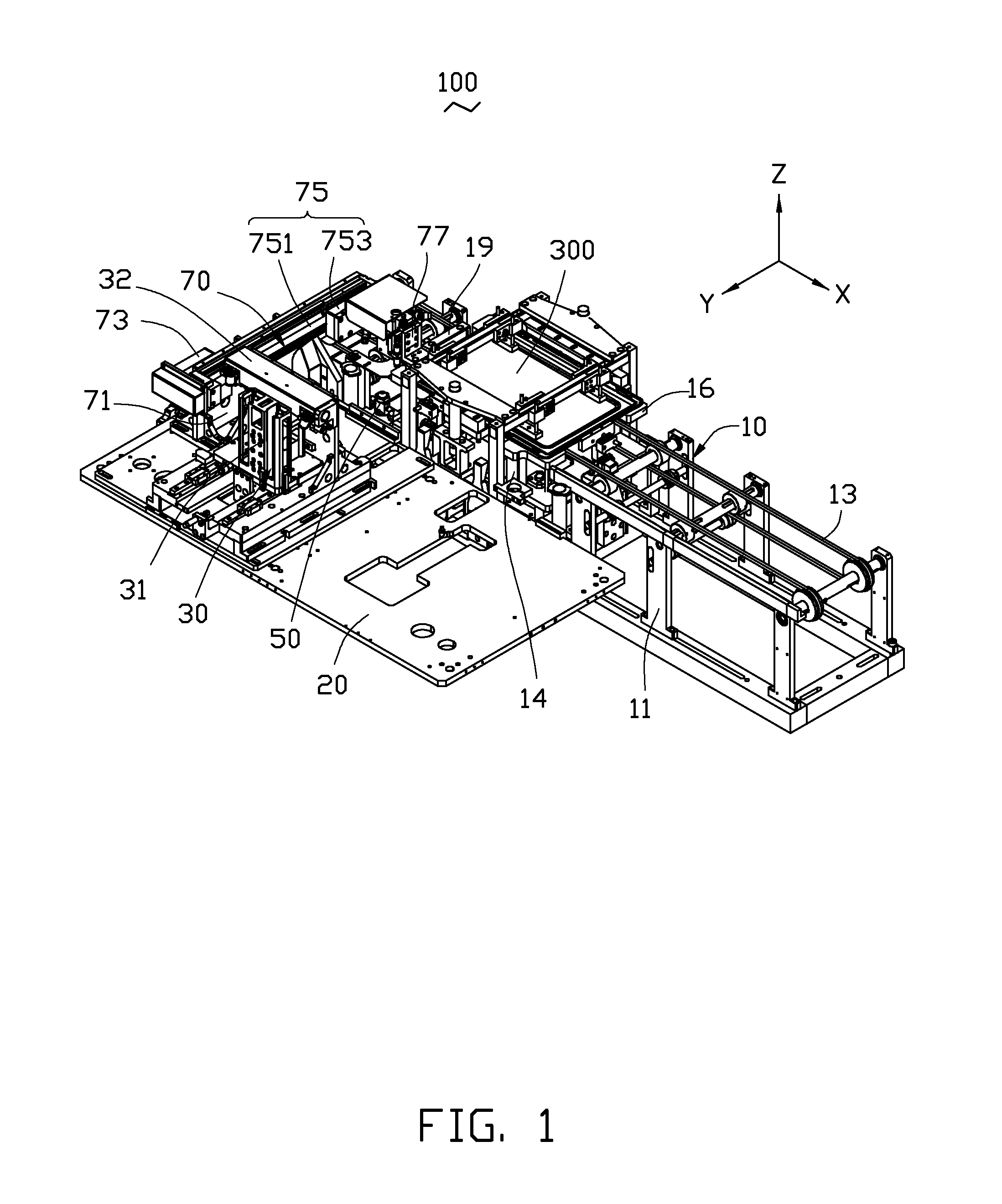
[0014]FIG. 1 shows one embodiment of a bonding device 100, for bonding a first workpiece 200 (shown in FIG. 4) to a second workpiece 300. The bonding device 100 includes a first feeding mechanism 10, a mounting platform 20. a second feeding mechanism 30, a glue spraying mechanism 50, and a bonding mechanism 70. The first feeding mechanism 10 is configured to feed the second workpiece 300 to a preset bonding position. The mounting platform 20 is located beside the first feeding mechanism 10. The second feeding mechanism 30 is mounted on the mounting platform 20, and is configured to feed the first workpiece 200 to the second workpiece 300. The g...


PUM


Abstract

A bonding device includes a first feeding mechanism, a second feeding mechanism, a glue spraying mechanism positioned between the first feeding mechanism and the second feeding mechanism, and a bonding mechanism. The first feeding mechanism comprises a mounting frame and a transmission belt mounted on the mounting frame. The second feeding mechanism includes a support frame, a feeding member positioned on the support frame, a positioning plate mounted on the support frame and located below the feeding member, and a first driver connected to the positioning plate. The feeding member vertically defines at least one feeding groove. The positioning plate defines a matching groove matching with the first workpiece The bonding mechanism includes a second driver and a suction member connected to the second driver.

Description

BACKGROUND[0001]1. Technical Field[0002]The present disclosure relates to bonding devices, and particularly to an automatic bonding device.[0003]2. Description of Related Art[0004]In bonding electronic components, two workpieces need to be bonded together. When in bonding, adhesive is manually coated on one workpiece, and then an another workpiece is adhered to the aforementioned workpiece. However, manually bonding of the workpieces wastes a large amount of labor and time, and the corresponding cost is high. In addition, a bonding accuracy of the workpieces is relatively low.[0005]Therefore, there is room for improvement in the art.BRIEF DESCRIPTION OF THE DRAWINGS[0006]The components in the drawings are not necessarily drawn to scale, the emphasis instead being placed upon clearly illustrating the principles of the present disclosure. Moreover, in the drawings, like reference numerals designate corresponding parts throughout several views.[0007]FIG. 1 is an assembled, isometric vi...

Claims


Application Information

Patent Timeline
IPC IPC(8): B32B37/00
CPCB32B37/0046H01L24/80B29C65/7805B29C65/7864B29L2031/3481F16B11/006Y10T156/1744
Inventor WANG, DING-XIANGDUAN, HENG
Owner FU DING ELECTRONICSAL TECH JIASHAN
Why Eureka
Try Eureka