Window component stock indexing

a window component and component stock technology, applied in the field of insulating glass units, can solve the problems of igus failure, limited production rate, vapor leakage path, etc., and achieve the effect of avoiding excess waste, rapid switching to different width strip materials, and avoiding waste of time and materials

Inactive Publication Date: 2009-11-03
GED INTEGRATED SOLUTIONS
View PDF31 Cites 35 Cited by
  • Summary
  • Abstract
  • Description
  • Claims
  • Application Information

AI Technical Summary

Benefits of technology

[0017]A method of changing elongated window component widths in an elongated window component production line reduces the time required for the change. In this method, a sheet stock coil with a first width is automatically indexed to an uncoiling position. The sheet stock having the first width is provided to a downstream processing station for processing. The sheet stock having the first width is severed. A sheet stock coil with a second width is automatically indexed to the uncoiling position while the sheet stock having the first width is being processed by the downstream processing station. The processing of the sheet stock having the first width is completed at the downstream processing station and the downstream processing station is automatically adjusted for processing of the sheet stock having the second width. The sheet stock having the second width is provided to the downstream processing station for processing.
[0020]The disclosed system has significant advantages over the system disclosed in U.S. Pat. No. 5,361,476 to Leopold. In that system an entire first spacer frame unit was scrapped each time a new roll was threaded into the system. That first frame was only scrapped, however, after dessicant and adhesive were applied to the frame resulting in waste in both time and materials. The disclosed system avoids excess waste by use of a short piece of scrap frame material that is removed from the system conveyor prior to the dessicant application station.
[0021]The '476 patent has a single supply of strip mounted at the beginning of the frame fabrication system. The present system utilizes an automated strip changeover system. Whereas the prior system might take up to 15 minutes to switch in a new roll of strip material once a preceding strip has been exhausted, the present system achieves changeover in less than one minute. Additionally the reliance on operators for changeover increased the possibility in operator error in set up that is avoided by the disclosed system.
[0022]The rapid changeover from one roll of strip material to a next roll and the ability to rapidly switch to different width strip material has resulted in efficiencies not achievable in the prior art. In the prior art, the fact that a whole roll of spacer material was used before a change meant that window construction was dependent on receipt of a large batch of frames of a given width. This placed constraints on subsequent manufacturing processes that could be performed and these constraints were not necessarily convenient or compatible with a desire to most efficiently fill customer orders. Use of the presently disclosed system allows rapid changover from one width strip to a next so that repair units for example can be built as needed to replace damaged window units as they occur. The system produces less work in process and real time response to customer orders in a way that increases total manufacturing throughput.

Problems solved by technology

IGUs have failed because atmospheric water vapor infiltrated the sealant barrier.
Reduced sealant at the frame corners tended to cause vapor leakage paths.
These were all manual operations which limited production rates.
Accordingly, fabricating IGUs from these frames entailed generating appreciable amounts of scrap and performing inefficient manual operations.
In spacer frame constructions where the roll forming occurred immediately before the spacer assembly was completed, sawing, desiccant filling and frame element end plugging operations had to be performed by hand which greatly slowed production of units.
That first frame was only scrapped, however, after dessicant and adhesive were applied to the frame resulting in waste in both time and materials.
The rapid changeover from one roll of strip material to a next roll and the ability to rapidly switch to different width strip material has resulted in efficiencies not achievable in the prior art.
This placed constraints on subsequent manufacturing processes that could be performed and these constraints were not necessarily convenient or compatible with a desire to most efficiently fill customer orders.

Method used


Image

  • Window component stock indexing
  • Window component stock indexing
  • Window component stock indexing

Examples


Embodiment Construction

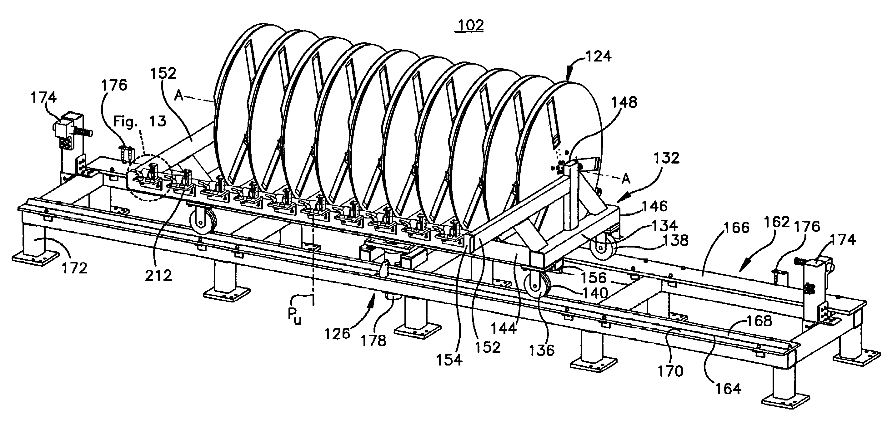
[0078]The drawing Figures and following specification disclose a method and apparatus for producing elongated window components 8 used in insulating glass units. Examples of elongated window components include spacer assemblies 12 and muntin bars 130 that form parts of insulating glass units. The new method and apparatus are embodied in a production line which forms sheet metal ribbon-like stock material into muntin bars and / or spacers carrying sealant and desiccant for completing the construction of insulating glass units. While the elongated window components illustrated as being produced by the disclosed method and apparatus are spacers, the claimed method and apparatus may be used to produce any type of elongated window component, including muntin bars.

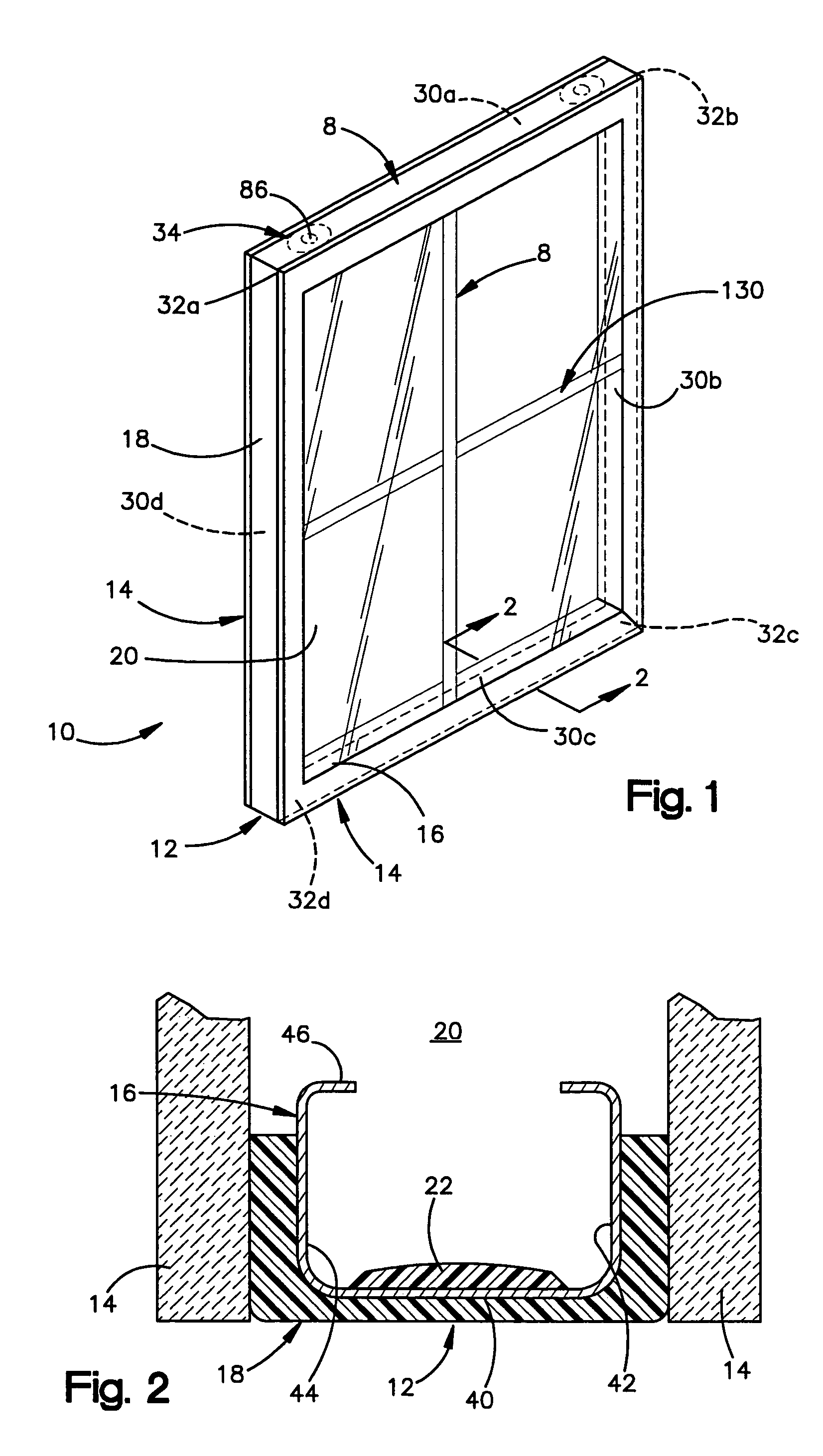
[0079]The Insulating Glass Unit

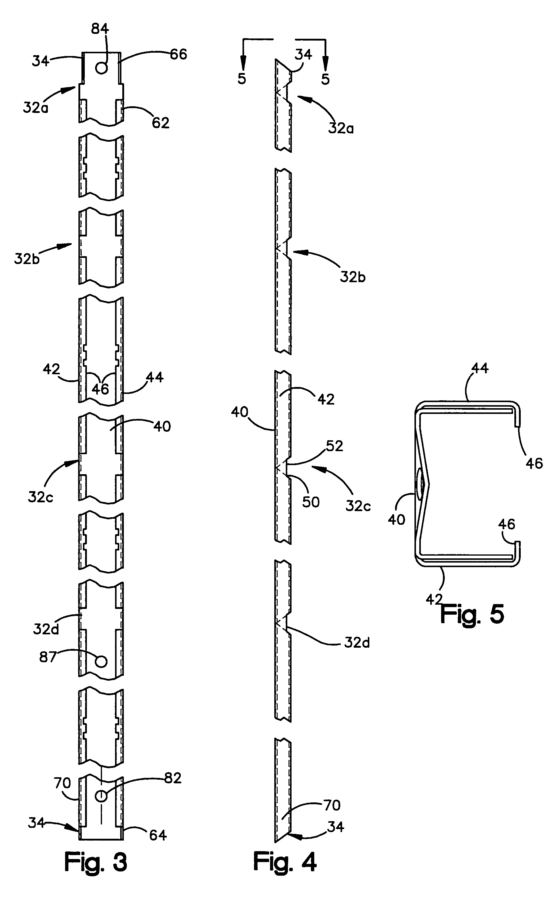
[0080]An insulating glass unit 10 constructed using the method and apparatus of the present invention is illustrated by FIGS. 1-6 as comprising a spacer assembly 12 sandwiched between glass sheets, o...


PUM

PropertyMeasurementUnit
movementaaaaaaaaaa
widthaaaaaaaaaa
widthsaaaaaaaaaa

Abstract

A stock supply station for use in a insulated glass unit component production line includes a plurality of rotatable sheet stock coils, an indexing mechanism, and an uncoiling mechanism. The indexing mechanism is coupled to the sheet stock coils for indexing a selected one of the sheet stock coils to an uncoiling position. The uncoiling mechanism selectively uncoils sheet stock from a sheet stock coil indexed to the uncoiling position to thereby provide sheet stock to a downstream processing station.

Description

CROSS REFERENCE TO RELATED APPLICATIONS[0001]The present application claims priority from U.S. provisional application Ser. No. 60 / 614,308 entitled “Window Component Stock Indexing” filed Sep. 29, 2004 and which is incorporated herein by reference.FIELD OF THE INVENTION[0002]The present invention relates to insulating glass units and more particularly to a method and apparatus for indexing elongated window component stock in an elongated window component production line.BACKGROUND OF THE INVENTION[0003]Insulating glass units (IGUs) are used in windows to reduce heat loss from building interiors during cold weather. IGUs are typically formed by a spacer assembly sandwiched between glass lites. A spacer assembly usually comprises a frame structure extending peripherally about the unit, a sealant material adhered both to the glass lites and the frame structure, and a desiccant for absorbing atmospheric moisture within the unit. The margins or the glass lites are flush with or extend sl...

Claims


Application Information

Patent Timeline
Patent Type & Authority Patents(United States)
IPC IPC(8): B23P17/00B65H19/10
CPCB21D53/74E06B3/67304E06B3/67365B65H16/106Y10T29/5136B65H2301/44921B65H2701/379E06B3/67308Y10T29/5198Y10T29/49829Y10T29/5197Y10T29/534Y10T29/49625Y10T29/49623Y10T29/53526Y10T29/49789E06B3/54Y10T29/49Y10T83/0405Y10T83/141Y10T83/902
Inventor CALCEI, TOMKHALFOUN, MOHAMEDJAMES, BRIAN G.MCGLINCHY, TIMOTHY B.GRISMER, JOHNSHEPHERD, II, ROBERT R.
Owner GED INTEGRATED SOLUTIONS
Why Eureka
Try Eureka