Microcomputer and method of testing same

a microcomputer and memory technology, applied in the field of microcomputers, can solve the problems of long test time, high failure rate of memory, and inability to test memory, so as to reduce the number of pins to be connected to the test apparatus, shorten the test time, and reduce the size

Inactive Publication Date: 2005-09-22
NEC ELECTRONICS CORP
View PDF4 Cites 34 Cited by
  • Summary
  • Abstract
  • Description
  • Claims
  • Application Information

AI Technical Summary

Benefits of technology

[0012] In accordance with the present invention, the memory and the logical circuit are tested simultaneously, thereby making it possible to shorten test time. In addition, a large number of switching circuits is made unnecessary to thereby achieve a reduction in size. Further, the number of pins to be connected to a test apparatus can be reduced by conducting a test based upon the test ROM within the microcomputer. As a result, the number of microcomputers connectable to a single test apparatus can be increased and

Problems solved by technology

However, when the failure rates of the memory and logic are compared, it is found that the failure rate is higher for the memory, which has a large number of constituent elements.
Consequently, total test time is the sum of memory test time and logical circuit test time and a problem which arises is that test time is lengthy.
Further, the time required to test the memory is much longer than that required to test the logical circuit.
This means that if a defect is found with testing of the logical circuit after the memory has been tested, then the test of the memory performed first represents time wasted.
Since switching circuits 190 are required in a number equivalent to the number of pins necessary to input the test pattern, a problem which arises is that the microcomputer has an architecture of large size.
However, sinc

Method used


Image

  • Microcomputer and method of testing same
  • Microcomputer and method of testing same
  • Microcomputer and method of testing same

Examples


first embodiment

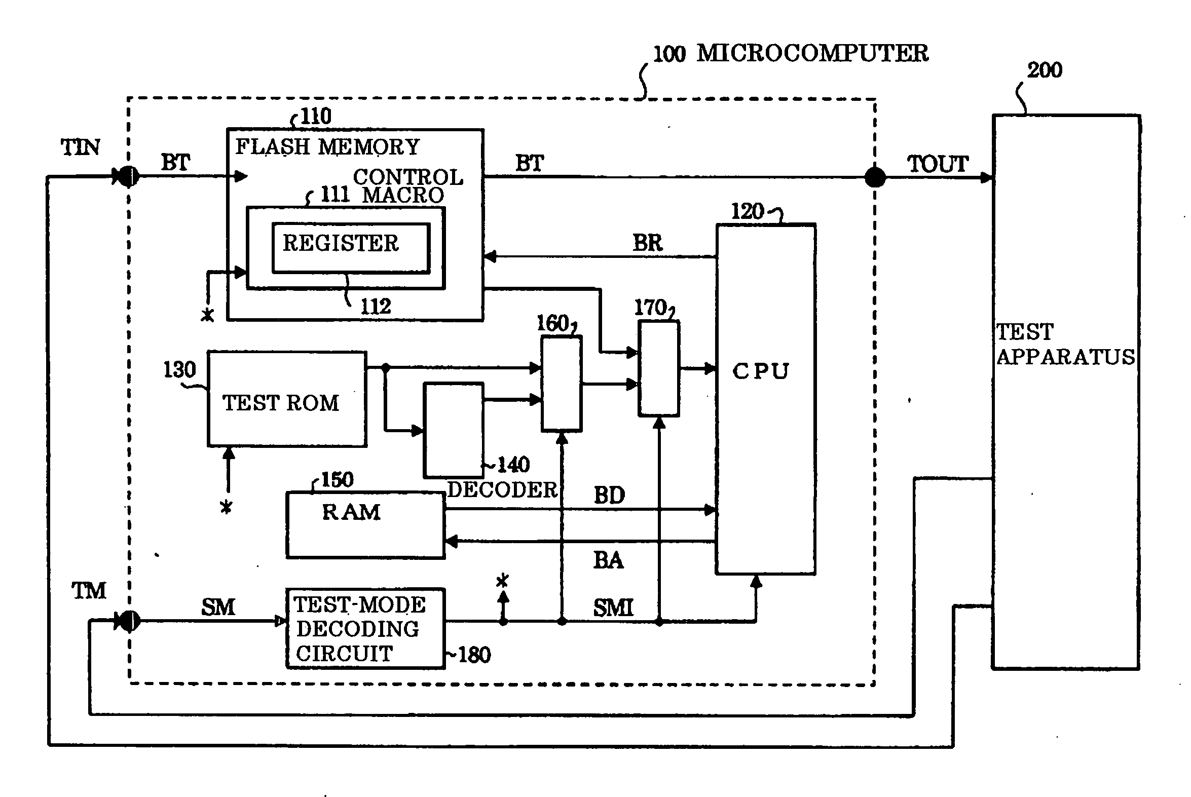
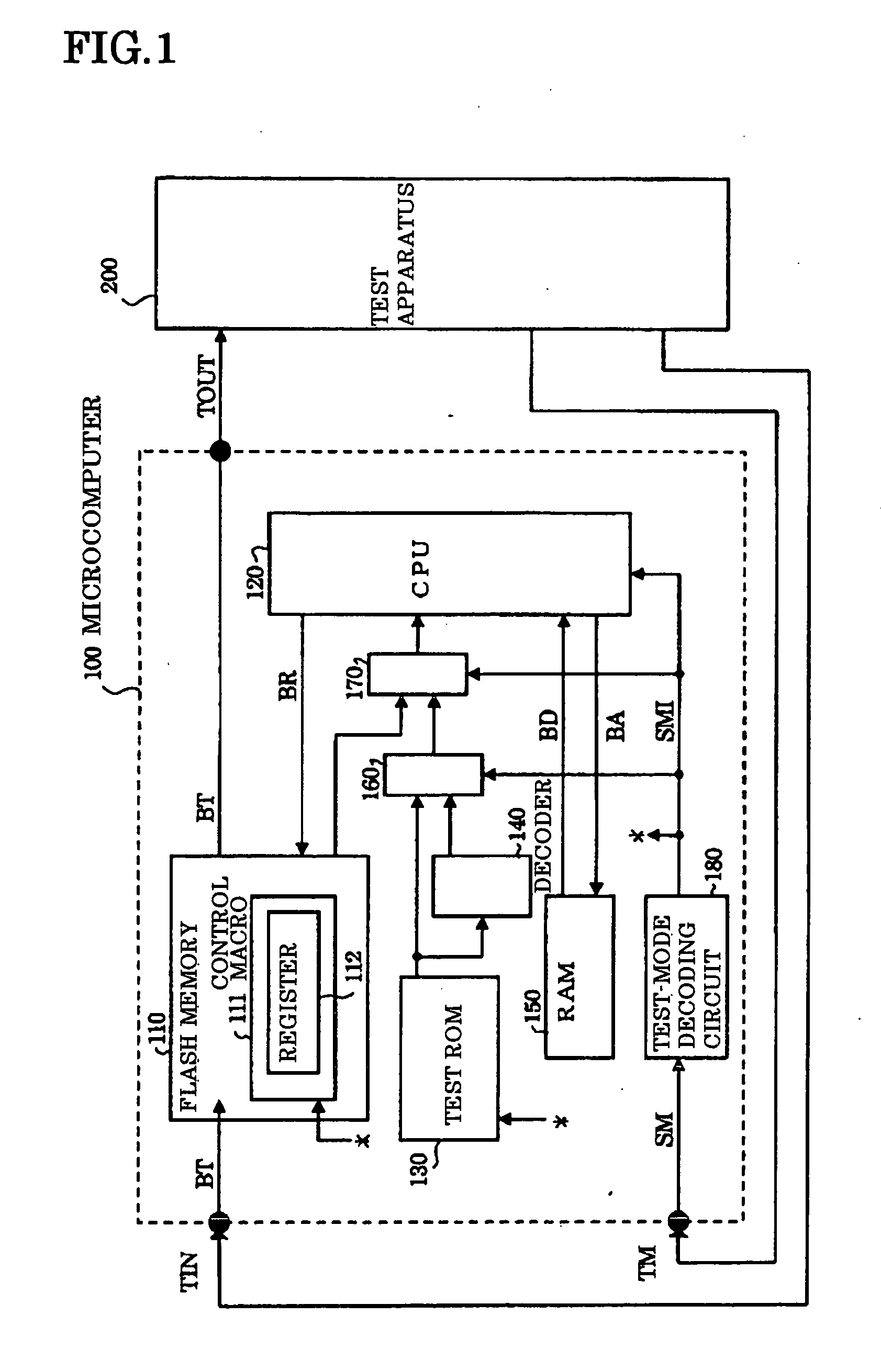
[0019] A first embodiment of the invention will be described with reference to FIG. 1, which is a block diagram illustrating the principal components of a microcomputer 100 having an internal flash memory 110 in accordance with the present invention.

[0020] As shown in FIG. 1, the microcomputer 100 includes the flash memory 110, which has a control macro 111 equipped with an internal register 112, and a CPU 120 for controlling the control macro 111 of the flash memory 110 to thereby execute prescribed operations beginning with writing and reading of data to and from the flash memory 110. The flash memory 110 and CPU 120 constitute a memory and a logical circuit, respectively, to be tested in accordance with the present invention. A test input terminal TIN and a test output terminal TOUT connected to an external test apparatus 200 have been connected to the flash memory 110 by a special-purpose test bus BT. A test pattern from the test apparatus 200 that has entered from the test inp...

second embodiment

[0028]FIG. 3 is a block diagram of a microcomputer 100A according to a second embodiment, in which components identical with those of the first embodiment are designated by like reference characters. As shown in FIG. 3, the microcomputer 100A includes a flash memory 110, which serves as the memory and has a control macro 111 equipped with an internal register 112, and a CPU 120 serving as the logical circuit for controlling the control macro 111 of the flash memory 110 to thereby execute prescribed operations beginning with writing and reading of data to and from the flash memory 110. In the second embodiment, the test input terminal TIN and test output terminal TOUT connected to the external test apparatus have been connected to the CPU 120 by the special-purpose test bus BT. Thus it is possible to input and output a test signal between the CPU 120 and the test apparatus 200. Further, the CPU 120 is connected to the flash memory 110 by the register setting bus BR, which is bi-direc...


PUM


Abstract

A microcomputer includes a memory such as a flash memory; a logical circuit such as a CPU; a test ROM storing a test program for testing at least the logical circuit; and recording means capable of storing, as a flag, the result of testing at least one of the memory and logical circuit. The memory and the logical circuit are tested simultaneously to shorten test time. The test-result flag is checked upon being stored. When the flag indicates failure of the logical circuit, testing of the memory is aborted, and vice versa.

Description

BACKGROUND OF THE INVENTION [0001] 1. Field of the Invention [0002] This invention relates to a microcomputer having a memory such as a flash memory and a logical circuit such as a CPU for executing logical operations. More particularly, the invention relates to a microcomputer that is capable of undergoing a test of the memory and a test of the logical circuit in a short period of time. [0003] 2. Description of the Related Art [0004] When a microcomputer incorporating a memory such as a flash memory, which is an electrically rewritable non-volatile memory, is tested, either the memory or the logic such as the CPU that executes logical operations is tested first. Then, when the item tested has been found to be acceptable, the other item is tested. Whichever of the memory or logic is tested first is not uniquely decided. However, when the failure rates of the memory and logic are compared, it is found that the failure rate is higher for the memory, which has a large number of constit...

Claims


Application Information

Patent Timeline
IPC IPC(8): G01R31/28G06F11/00G06F12/16G06F11/22G06F11/273G06F15/78G11C29/08
CPCG01R31/31707G11C2029/0401G11C29/08G06F11/2635
Inventor TOTSUKA, KAZUFUMI
Owner NEC ELECTRONICS CORP
Why Eureka
Try Eureka