Conductance valve and vacuum processing apparatus
a technology of vacuum processing apparatus and conductance valve, which is applied in the direction of valve details, valve arrangement, operating means/releasing devices, etc., can solve the problems of reducing the maintenance workability of the chamber, and achieve the effect of reducing the space of the conductance valve and good maintenance workability
- Summary
- Abstract
- Description
- Claims
- Application Information
AI Technical Summary
Benefits of technology
Problems solved by technology
Method used
Image
Examples
first embodiment
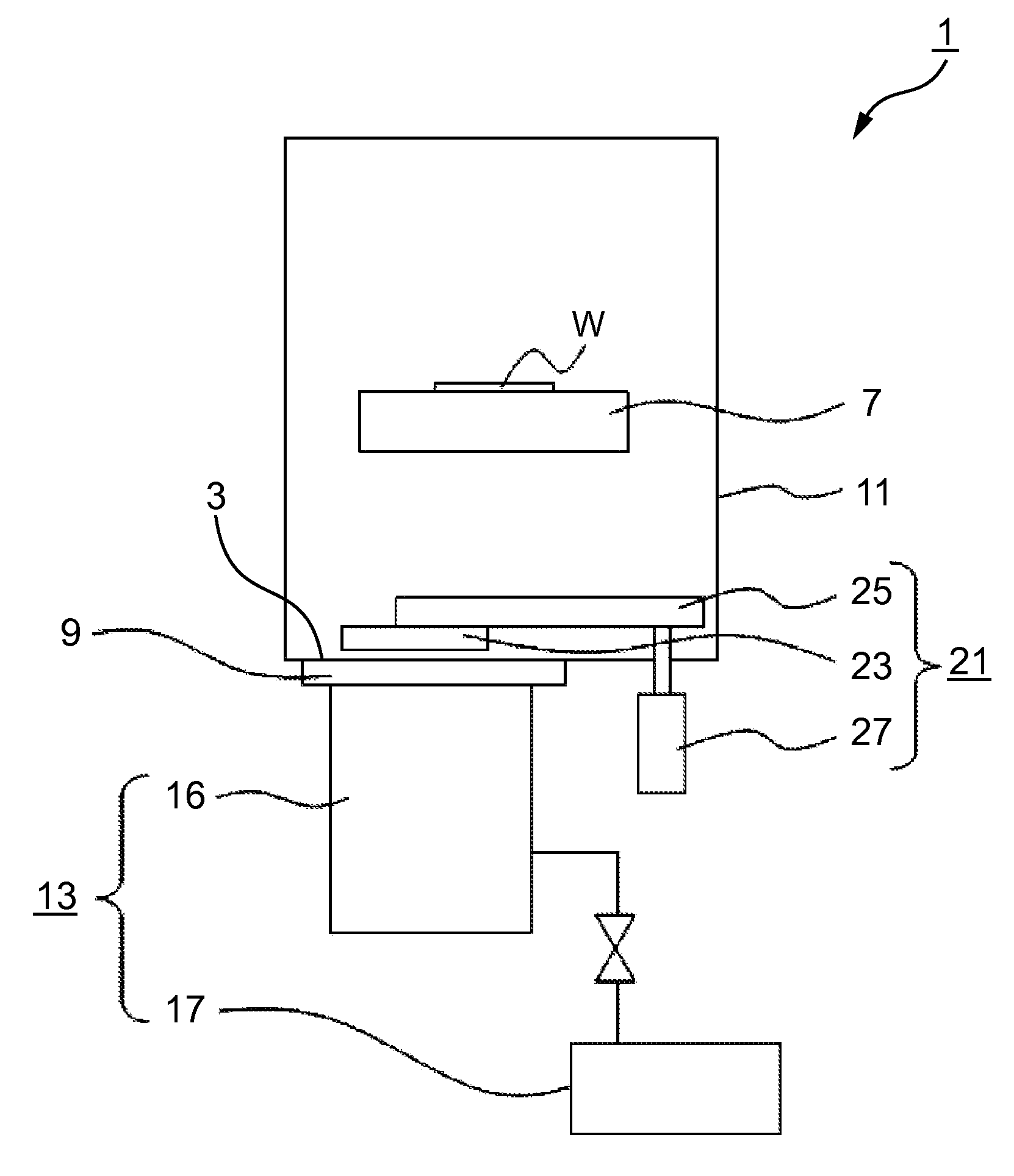
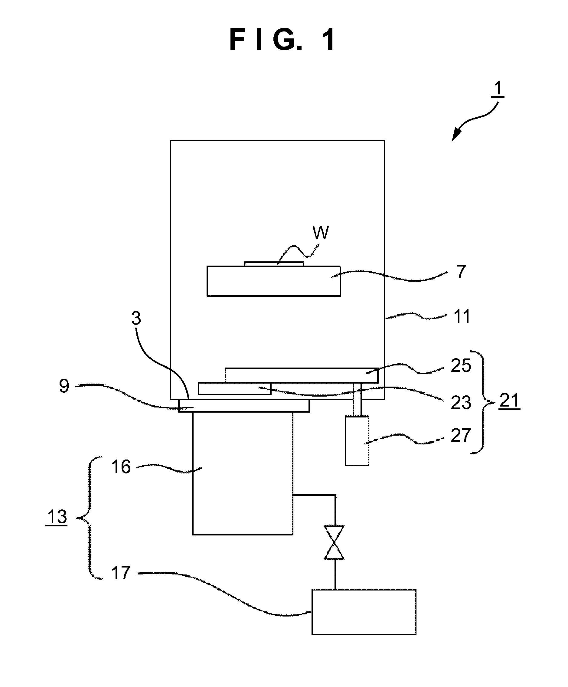
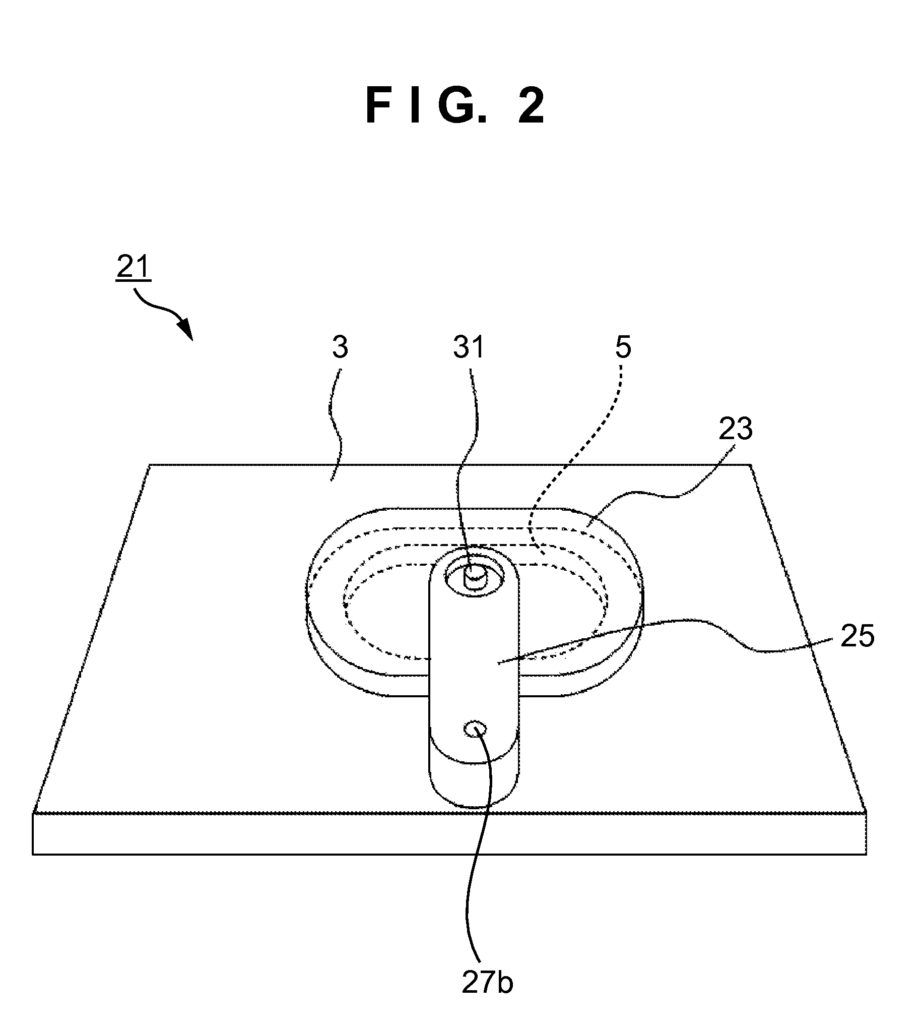
[0022]FIG. 1 is a schematic view showing a vacuum processing apparatus according to the A vacuum processing apparatus 1 according to the embodiment includes a vacuum vessel 11, exhaust device 13, and conductance valve 21. The vacuum vessel 11 incorporates a substrate holder 7 capable of placing a substrate W, and is configured to be able to perform predetermined vacuum processing such as deposition or annealing for a substrate. An attaching portion 9 is disposed at a bottom 3 of the vacuum vessel 11 to connect the exhaust device 13. An opening 5 is formed in the attaching portion 9 of the exhaust device 13 that is disposed on the bottom 3 of the vacuum vessel 11. As a vacuum pump, the exhaust device 13 includes, for example, a turbo-molecular pump (TMP) 16 and a dry pump 17 which reduces the back pressure of the TMP 16. The conductance valve 21 is disposed to adjust the opening degree of the opening 5 formed in part (bottom 3) of the vacuum vessel 11. As will be described later, th...
second embodiment
[0037]FIG. 7C shows a state in which the valve body 43 moves to a position (opening position) where the amount by which the valve body 43 blocks the opening 5 is smallest. The shaft member 31 is disposed at a position shifted to one side from the center position of the valve body 43. This can increase, for example, the area by which a swing arm 25 and the valve body 43 overlap each other at the opening position, as shown in FIG. 7C. Since the swing arm 25 and valve body 43 are arranged to overlap each other, the area necessary to arrange the conductance valve with respect to the size of the opening 5 can be decreased, saving the space. In the second embodiment, at the opening position (FIG. 7C), the longitudinal direction of the valve body 43 and that of the swing arm 25 become parallel to each other, and cross that of the opening 5 perpendicularly. This arrangement is advantageous for downsizing and space-saving of the conductance valve.
[0038]FIGS. 8A to 8C show the third embodimen...
third embodiment
[0041]In the third embodiment, the ratio of the driving shaft-side pulley 37a and valve body-side pulley 37b is set so that the longitudinal direction of the valve body 53 moves in parallel with the longitudinal direction of the opening 5. Also, the driving shaft 27b is arranged so that the swing arm 55 becomes parallel to the longitudinal direction of the opening 5 when the valve body 53 is at an intermediate position (FIG. 8B) between the closed position (FIG. 8A) and the opening position (FIG. 8C). This arrangement of the driving shaft 27b is advantageous for downsizing and space-saving of the conductance valve because the valve body 53 can be arranged at symmetrical positions at the closed position (FIG. 8A) and the opening position (FIG. 8C). Further, this arrangement of the driving shaft 27b is advantageous for downsizing and space-saving of the conductance valve because, even when the valve body 53 moves by the moving amount d in the Y direction, as shown in FIG. 8B, it does ...
PUM
 Abstract
Description
Claims
Application Information
 - R&D
- Intellectual Property
- Life Sciences
- Materials
- Tech Scout
- Unparalleled Data Quality
- Higher Quality Content
- 60% Fewer Hallucinations
Browse by: Latest US Patents, China's latest patents, Technical Efficacy Thesaurus, Application Domain, Technology Topic, Popular Technical Reports.
© 2025 PatSnap. All rights reserved.Legal|Privacy policy|Modern Slavery Act Transparency Statement|Sitemap|About US| Contact US: help@patsnap.com


