Vehicle lift device

a technology of lifting device and lifting platform, which is applied in the direction of lifting device, vehicle servicing/repairing, transportation and packaging, etc., can solve the problems of reducing the earthwork area of the maintenance site, reducing the area of the pit, and reducing the workability of the respective undulating link devi

Active Publication Date: 2020-10-29
YASUI KK
View PDF0 Cites 3 Cited by
  • Summary
  • Abstract
  • Description
  • Claims
  • Application Information

AI Technical Summary

Benefits of technology

[0026](g) When the vehicle support table of each of the raising/lowering devices is positioned at the lift-up position and an intersection of the first and second links is arranged to be higher than each of existing front and rear work floors, the triangular inter-link gap, which is formed immediately below the intersection and on the upper side of the work floor by being sandwiched by lower edges of the first and second links below the intersection, faces each of the front and rear work floors. When the raising/lowering device is lowered so that this triangular inter-link gap is displaced to be reduced, the worker does not exist below the descending vehicle, and it is possible to eliminate the risk that a foot is pinched in the inter-link gap that is displaced to be reduced.
[0027](h) Each of the links constituting the undulating link device of each of the raising/lowering devices is configured using the assembly of two link members that form a pair, and each of two link elements constituting each of the link in the raising/lowering device on the left side and each of two link elements constituting each of the links in t

Problems solved by technology

This means that an installation space for the undulating link device is increased in the maintenance work area so that it is difficult to secure a wide maintenance work space immediately below the lifted vehicle to improve the maintenance workability.
Therefore, the respective undulating link devices are arranged to be line-symmetric with each

Method used


Image

  • Vehicle lift device
  • Vehicle lift device
  • Vehicle lift device

Examples


Embodiment Construction

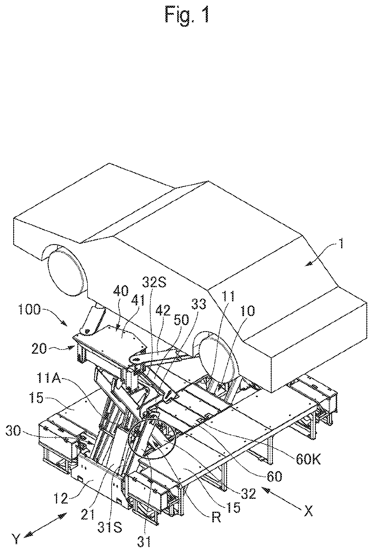
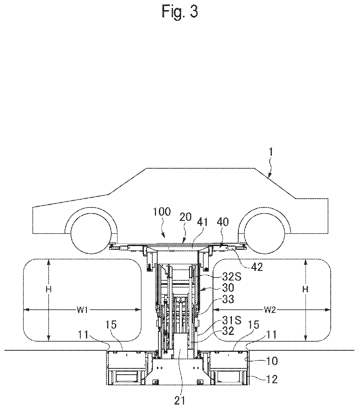
[0058]A vehicle lift device 100 is provided with a pair of left and right raising / lowering devices 20 on both sides in a left-right direction Y (vehicle width direction) (FIGS. 1, 12 to 17) orthogonal to an approach direction X (vehicle longitudinal direction) of a vehicle 1 (FIGS. 1, 12 to 17 in a maintenance work area where the vehicle 1 approaches and stops at a maintenance site as shown in FIGS. 1 to 4.

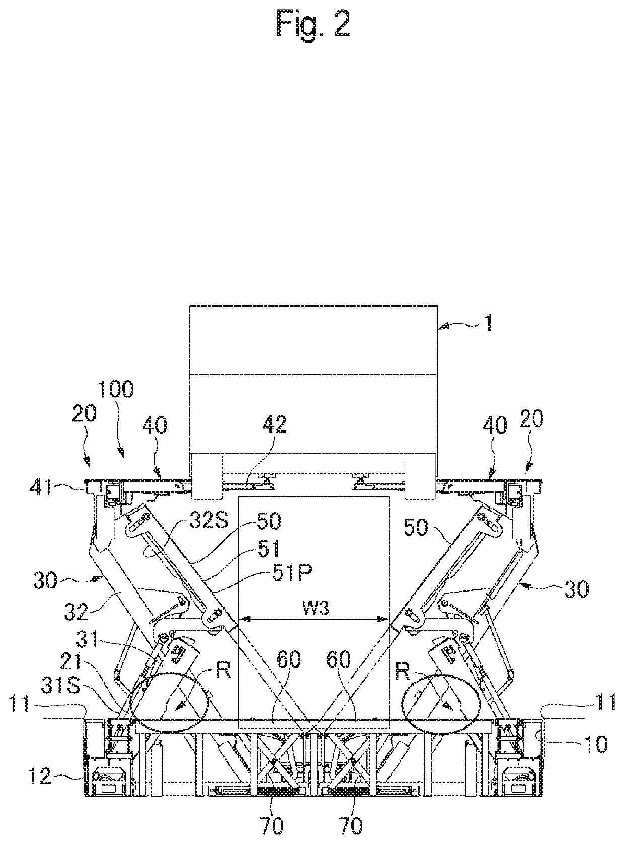
[0059]In the embodiment, a pit 10 (FIG. 2) is recessed in the maintenance work area defined on the floor of the maintenance site, and the pair of raising / lowering devices 20 are housed inside the pit 10.

[0060]Each of the raising / lowering devices 20 has an undulating link device 30 constituted by a plurality of links, and has a vehicle support table 40 (a lift table 41 and front and rear turning arms 42 and 42) which supports the vehicle and is mounted on the top of the undulating link device 30. Specifically, each of the vehicle support tables 40 has the lift table 41 provided on ...


PUM


Abstract

In a vehicle lift device, an undulating link device of each of the raising/lowering devices has each link displaced along the left-right direction orthogonal to an approach direction of a vehicle, and keeps a vehicle support table in a horizontal state to be raised and lowered only in the vertical direction.

Description

BACKGROUNDTechnical Field[0001]The present invention relates to a vehicle lift device.Related Art[0002]Conventionally, as described in Patent document 1, there is a vehicle lift device provided with a pair of left and right raising / lowering devices on both sides in a left-right direction orthogonal to an approach direction of a vehicle in a maintenance work area where the vehicle enters and stops at a maintenance site, each of the raising / lowering devices having an undulating link device constituted by a plurality of links and having a vehicle support table (for example, a lift table and a turning arm) that supports the vehicle mounted on the undulating link device.[0003]In the vehicle lift device described in Patent document 1, in the undulating link device of each of the raising / lowering devices, each link is displaced along the vehicle approach direction (in other words, a vehicle longitudinal direction).[0004]Patent document 1: JP 2018-203382 ASUMMARY[0005]The vehicle lift devic...

Claims


Application Information

Patent Timeline
IPC IPC(8): B66F7/06
CPCB66F7/0666B60S5/00B66F7/08B66F7/28B66F7/0691B66F2700/12
Inventor HORIMIZU, TOSHIHIDEMOCHIZUKI, TADASHI
Owner YASUI KK
Why Eureka
Try Eureka