Electronic device

Inactive Publication Date: 2014-07-03
TETABUWAN
View PDF4 Cites 18 Cited by
  • Summary
  • Abstract
  • Description
  • Claims
  • Application Information

AI Technical Summary

Problems solved by technology

SDI and HD-SDI are currently only available in professional equipm

Method used


Image

  • Electronic device
  • Electronic device
  • Electronic device

Examples


Embodiment Construction

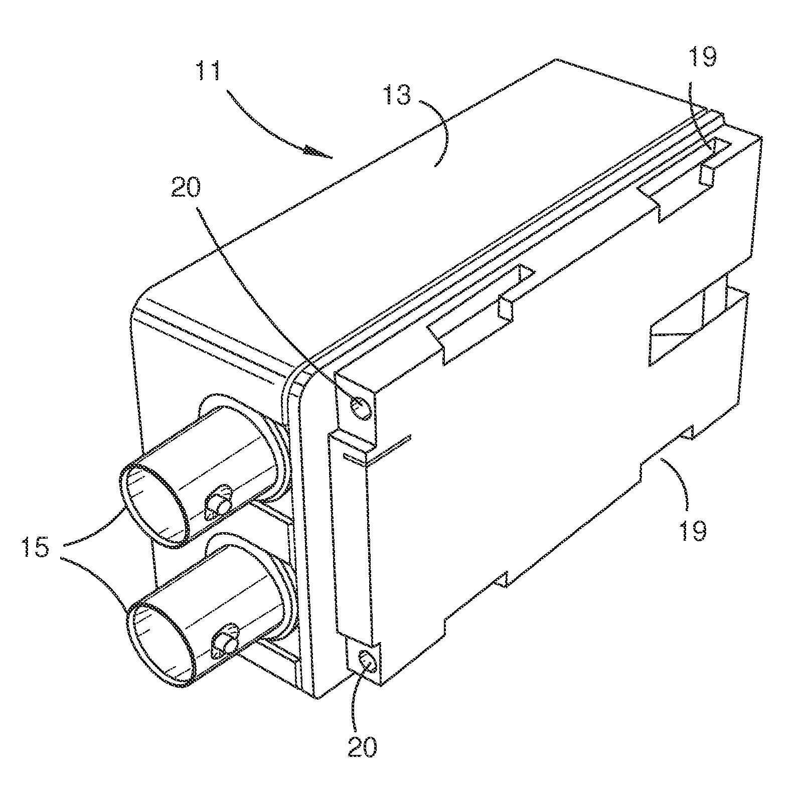
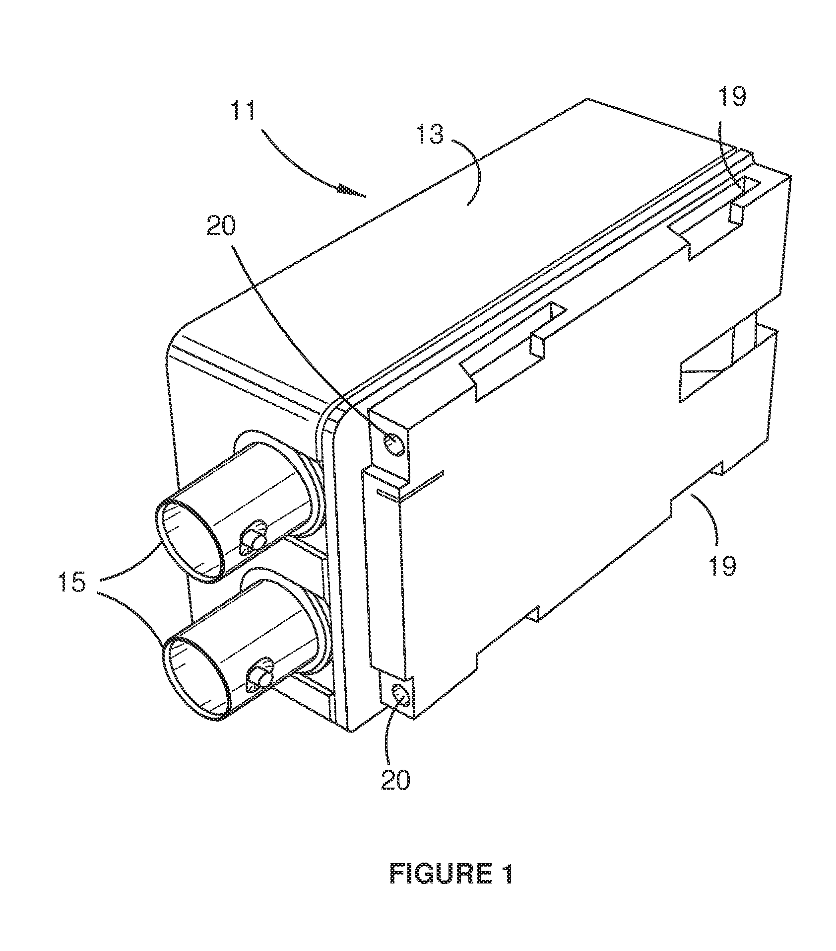
[0029]The video conversion device illustrated in FIGS. 1 to 3 is denoted generally as 11 and it is shown in FIG. 3 connected to a conventional video camera battery pack 12. Device 11 comprises a rectangular block shaped body 13 of generally similar proportions to the battery pack 12. Body 13 houses electronic circuitry for conversion of an HDMI signal fed through input terminal 14 to an SDI signal which is outputted through output terminals 15.

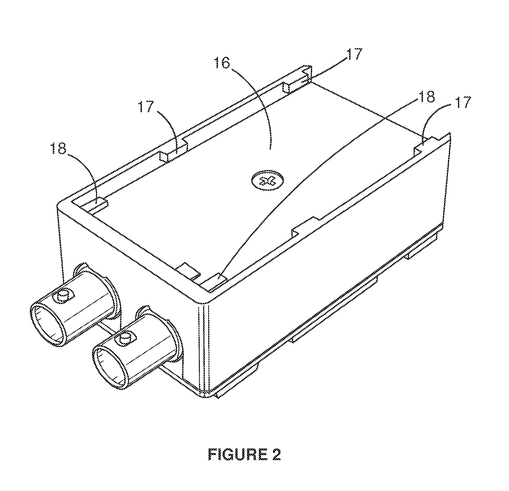
[0030]One side of body 13 is provided with four L-shaped slideway formations 19 designed to receive slides on a battery plate of a video camera (not shown) to form a push-on physical connection with the camera. The other side of body 13 is recessed at 16 and provided at the edges of the recess with four lugs or slide formations 17 which are complementary to the slideway formations 19 and identical to the formations of the video camera battery connection plate. Accordingly they can be fitted into the slideways formed in the base of battery pack...


PUM


Abstract

A video conversion device, containing electronic circuitry for conversion of a High Definition Multimedia Interface (HDMI) signal fed through input terminal to a Serial Digital Interface (SDI) signal which is outputted through output terminals, is connected to a conventional video camera battery pack. The body has four L-shaped slideway formations to receive slides on a battery plate to form a push-on physical connection with the camera. One side of the body is recessed, with four lugs or slide formations complementary to the slideway formations, at the edges of the recess, to be fitted into the slideways formed in the base of the battery pack to the slideway slots in the conversion device, and the battery pack can be quickly fitted to the conversion device via a push-on connection. The battery pack supplies power to the circuitry of the conversion device through terminals which is then supplied to the camera.

Description

TECHNICAL FIELD[0001]This invention relates to electronic devices and has particular but not exclusive application to electronic equipment used in capturing, monitoring, recording and transmitting video and audio material. Such equipment may be used professionally in studios or in the field or may be sold and used as consumer equipment.[0002]Video cameras and other equipment used in association with video cameras (such as motorised mounting devices, lights and monitors) are often battery powered using battery packs which can be mounted directly on the equipment through push-on connections provided by interfitting formations on the battery packs and the respective items of equipment. Accordingly, each of these items is usually powered by a separate battery which, once the battery is depleted, must be replaced by another battery during which time the device will be without power. One embodiment of the invention enables a simplification and improvement in the battery powering of such e...

Claims


Application Information

Patent Timeline
IPC IPC(8): H01M2/10H04N5/225
CPCH04N5/2251H01M2/1055H01R13/62905H01R31/065H02J7/0068H02J7/342Y02E60/10H01M50/213H02J7/007182H04N23/50
Inventor OVERLIESE, IANYOUNG, JEROMY MICHAELELLESON, DANIEL JOHN
Owner TETABUWAN
Why Eureka
Try Eureka