Ethernet optical terminal adapter and ethernet transmission method

A technology of an adaptation device and a transmission method, applied in the field of network communication, can solve the problems of waste of resources and high cost, and achieve the effect of saving resources

Inactive Publication Date: 2007-12-05
NEW H3C TECH CO LTD
View PDF0 Cites 14 Cited by
  • Summary
  • Abstract
  • Description
  • Claims
  • Application Information

AI Technical Summary

Problems solved by technology

[0008] The purpose of the present invention is to provide an Ethernet optical port adaptation device and an Ethernet transmission method, so as to solve the problem that if an existing user selects an optical transmission accessory when purchasing equipment, the task can be completed even if the electrical transmission is used afterwards Under the current situation, it is still only possible to use high-cost optical modules and lay optical fibers for optical transmission, resulting in a large waste of resources.

Method used


Image

  • Ethernet optical terminal adapter and ethernet transmission method
  • Ethernet optical terminal adapter and ethernet transmission method

Examples


Embodiment Construction
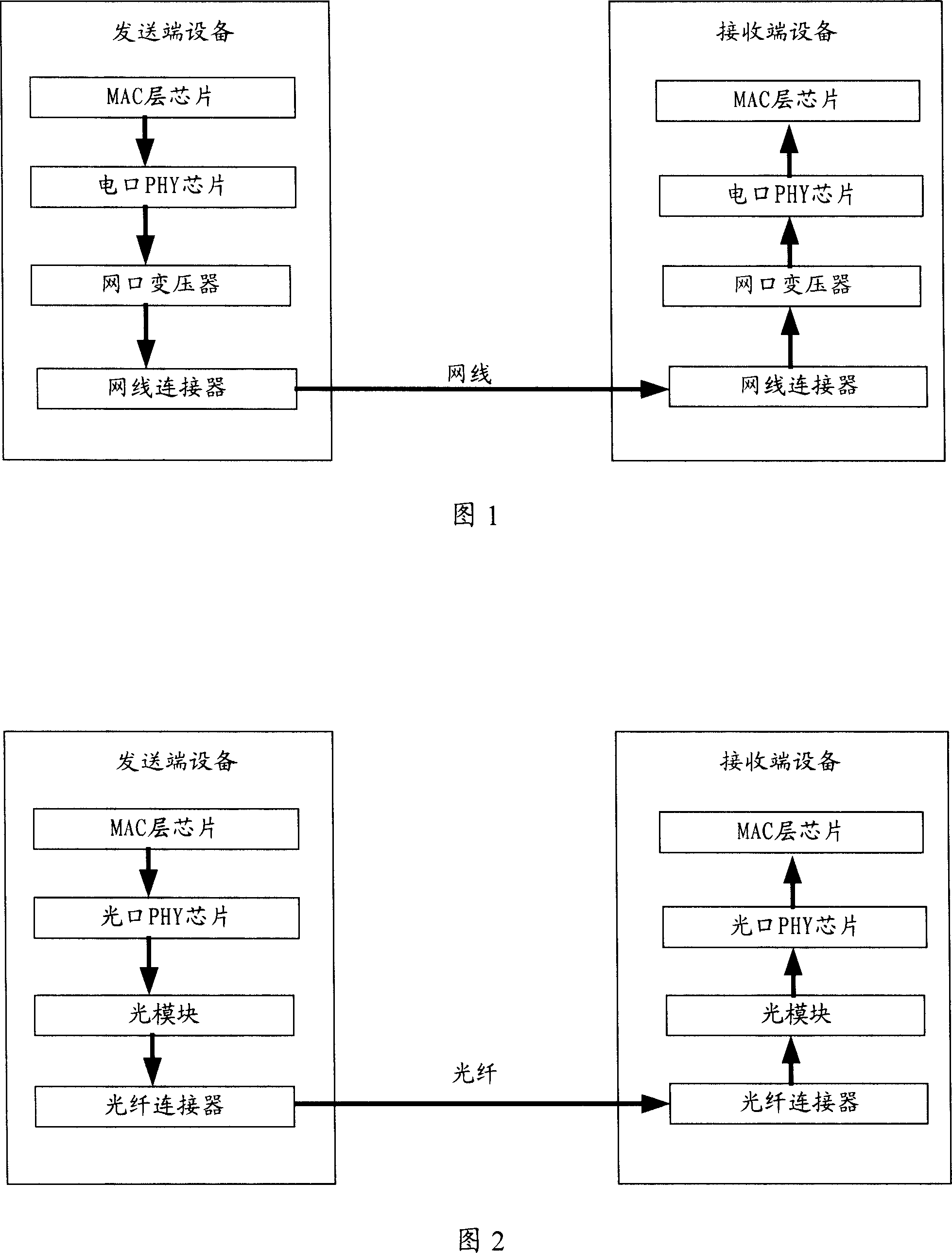
[0030] The core idea of ​​the present invention is to convert the digital signal output by the optical port PHY chip into an analog signal that can be transmitted by using an electrical transmission medium.

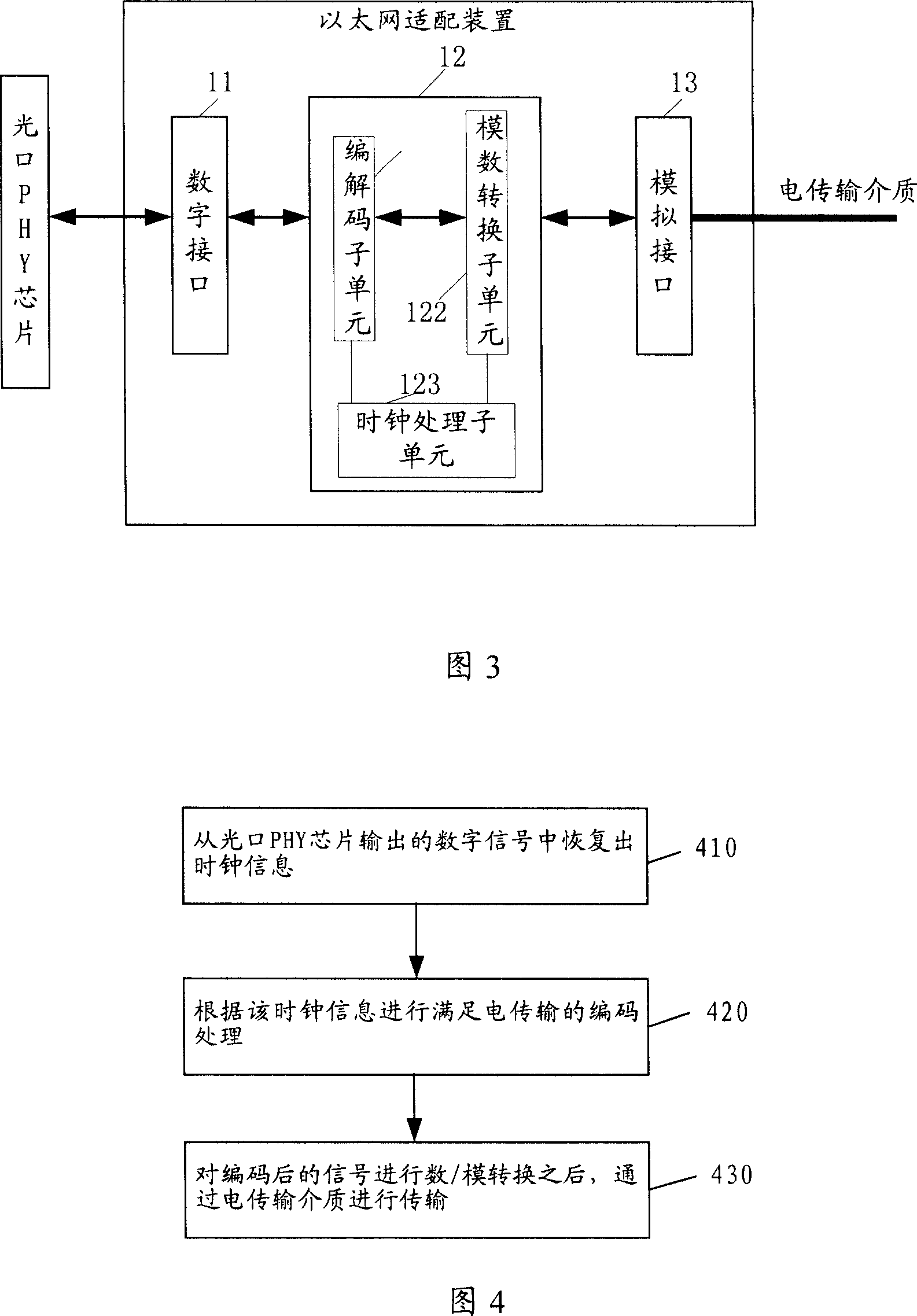
[0031] Please refer to FIG. 3 , which is a schematic structural diagram of an embodiment of an Ethernet optical port adapter device disclosed in the present invention.

[0032] One side of the Ethernet optical port adapter device performs digital signal interaction with the optical port PHY chip, and the other side performs analog signal interaction with the electrical transmission medium. The device specifically includes a digital interface 11 adapted to the optical port PHY chip, an analog interface 13 adapted to electrical transmission, and a physical layer conversion unit 12, which is used to convert the digital signal input by the optical port PHY chip into a digital interface suitable for The analog signal transmitted by electricity is sent through the analog interf...


PUM


Abstract

The invention discloses an Ethernet optical port adapter, comprising digital interface adapted to optical port PHY chip, and analog interface adapted to electric transmission, as well as physical layer conversion unit for converting the digital signals of the digital input interface of the optical port PHY chip into analog signals suitable to electric transmission and transmitting the analog signals via the analog interface; or converting the analog signals the analog interface receives into digital signals adapted to the optical port PHY chip and transmitting the digital signals to the optical port PHY chip. Thus, it can make the output signals of the optical port PHY chip transmitted via electric transmission medium so as to save resources.

Description

technical field [0001] The invention relates to the technical field of network communication, in particular to an Ethernet optical port adaptation device and an Ethernet transmission method. Background technique [0002] Currently, switches, routers and other equipment or host terminals mainly use optical fiber and ordinary network cables (or telephone lines) as two transmission media for data transmission. Due to the different transmission media, the specific data transmission process, physical layer PHY chip and other hardware are also the same. [0003] Please refer to FIG. 1 , which is a schematic diagram of an electrical transmission path of an existing receiving / transmitting device through a common network cable. According to the network layering protocol, the sending device transmits the data information from top to bottom, and the MAC layer chip outputs the MAC layer code stream to be sent to the electrical port PHY chip of the physical layer, and the electrical por...

Claims


Application Information

Patent Timeline
Patent Type & Authority Applications(China)
IPC IPC(8): H04L12/02H04B10/02H04L29/10H04B10/25
Inventor 于洋王玮刘汉斌许全会
Owner NEW H3C TECH CO LTD
Why Eureka
Try Eureka