
System and method for level translation in serial data interface

a serial data interface and level translation technology, applied in the direction of logic circuit coupling/interface arrangement, pulse technique, instruments, etc., can solve the problems of requiring ever more stringent control over various operational parameters, coupling capacitors preventing the passage of dc voltage levels, and at least two external components for each pair of differential serial lines, so as to achieve minimal attenuation of incoming signals, heightened sensitivity to the voltage levels of incoming signals, and preservation of compatibility

Active Publication Date: 2011-05-24
CADENCE DESIGN SYST INC
View PDF7 Cites 14 Cited by
  • Summary
  • Abstract
  • Description
  • Claims
  • Application Information

AI Technical Summary

Benefits of technology

[0009]It is an object of the present invention to provide an interface for preserving compatibility between an incoming signal and a receiver stage with heightened sensitivity to the voltage levels of the incoming signal, with minimal attenuation of the incoming signal and minimal reduction in signal bandwidth.
[0010]It is another object of the present invention to provide an on-chip serial interface for high speed differential data transfer between circuits which accomplishes a level shifting of the incoming common mode voltage to a level tolerable to highly sensitive devices of the receiving circuit with minimal attenuation of the incoming signal and minimal reduction in signal bandwidth.

Problems solved by technology

Many of those same advances, however, require ever more stringent control over various operational parameters, not the least of which is the level of common mode voltage that certain low voltage devices may safely tolerate.
An obvious drawback of this approach is that the coupling capacitors prevent the passage of DC voltage levels.
An additional drawback is that it requires at least two external components for each pair of differential serial lines.
Since the number of serial lines on an integrated circuit may be quite high, the number of external components may also become quite high, excessively so.
Such high voltage transistors, however, tend to be considerably slower than the thinner oxide transistors required for high speed applications.
Receiver circuits integrated with these higher voltage input stages may not even operate when their serial buses receive very high speed data streams in the range, for instance, of 10 Gbit / sec.
An additional drawback of this approach is that receiver circuits with the thicker oxide transistors are powered by higher supply voltages which lead to greater power dissipation.
This, however, adds undue power dissipation by the resistive elements.
Another drawback is the bandwidth reduction due to the resistive elements interacting with the parasitics of the given load capacitance.
Furthermore, the shifted voltage for the incoming voltage is determined necessarily by the input common mode voltage and for that reason cannot be well controlled.
Such signal attenuation is undesirable, especially in case of a long line, since the signal may already be greatly degraded as it is by the line channel.

Method used


Image

  • System and method for level translation in serial data interface
  • System and method for level translation in serial data interface
  • System and method for level translation in serial data interface

Examples


Embodiment Construction

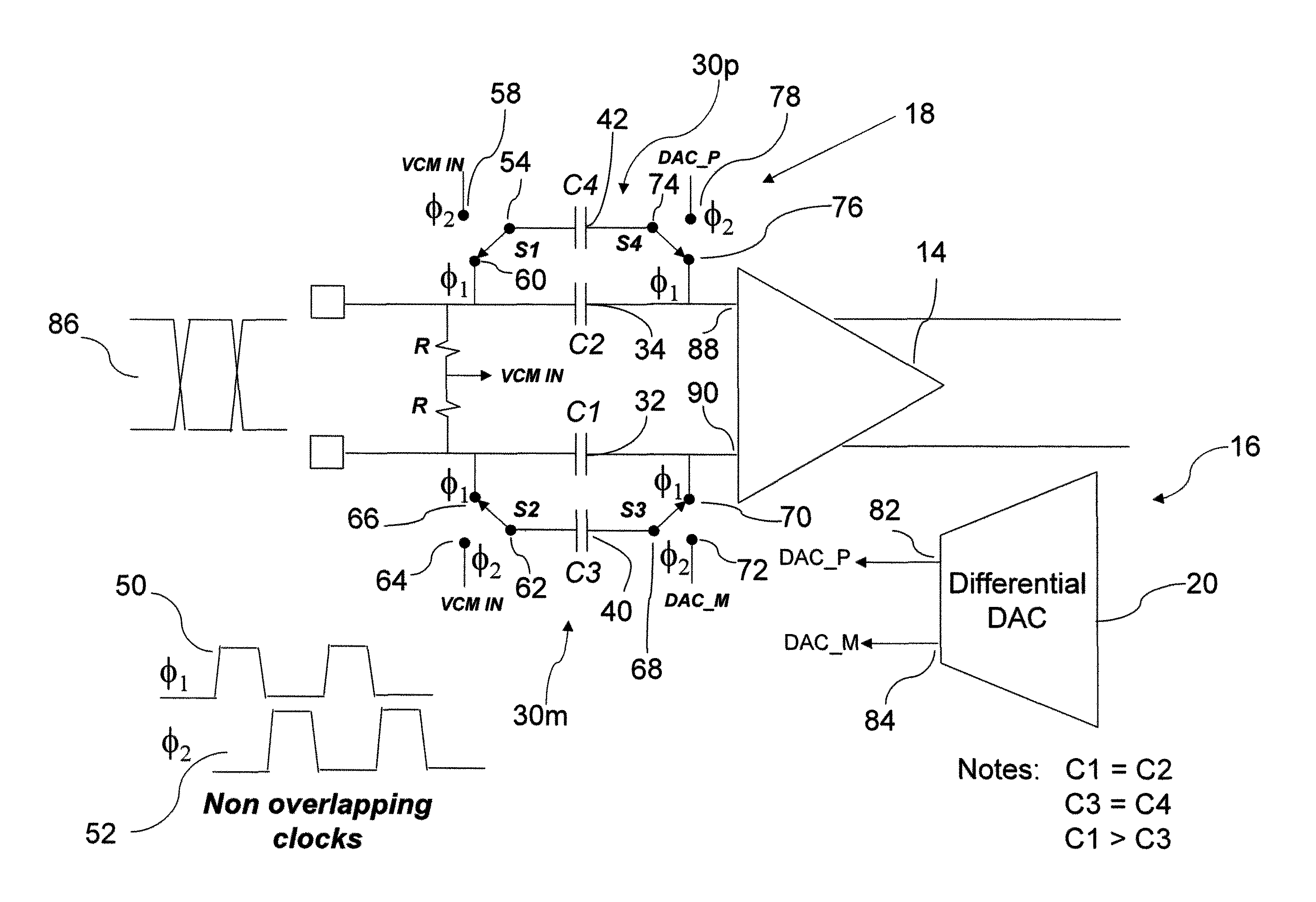
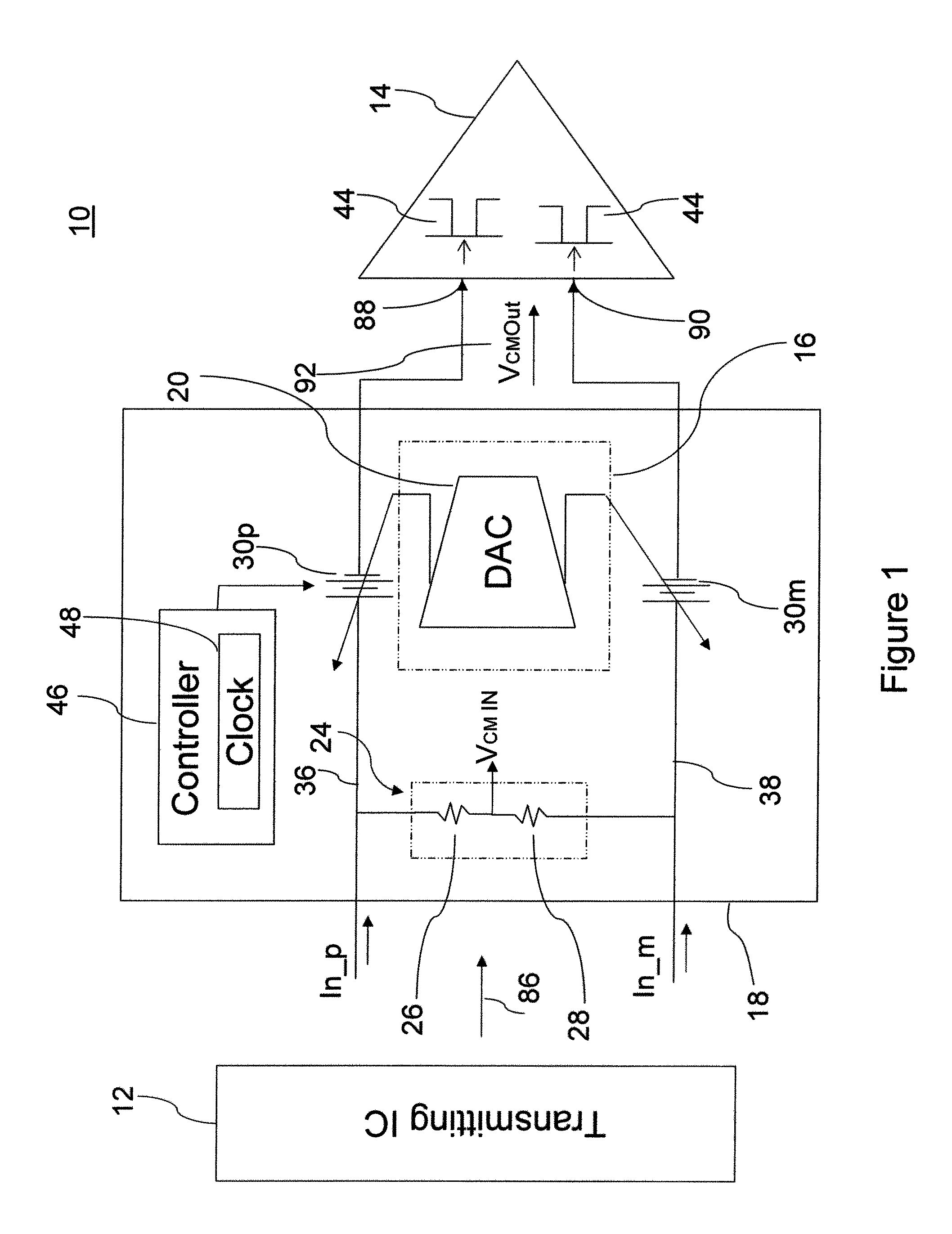
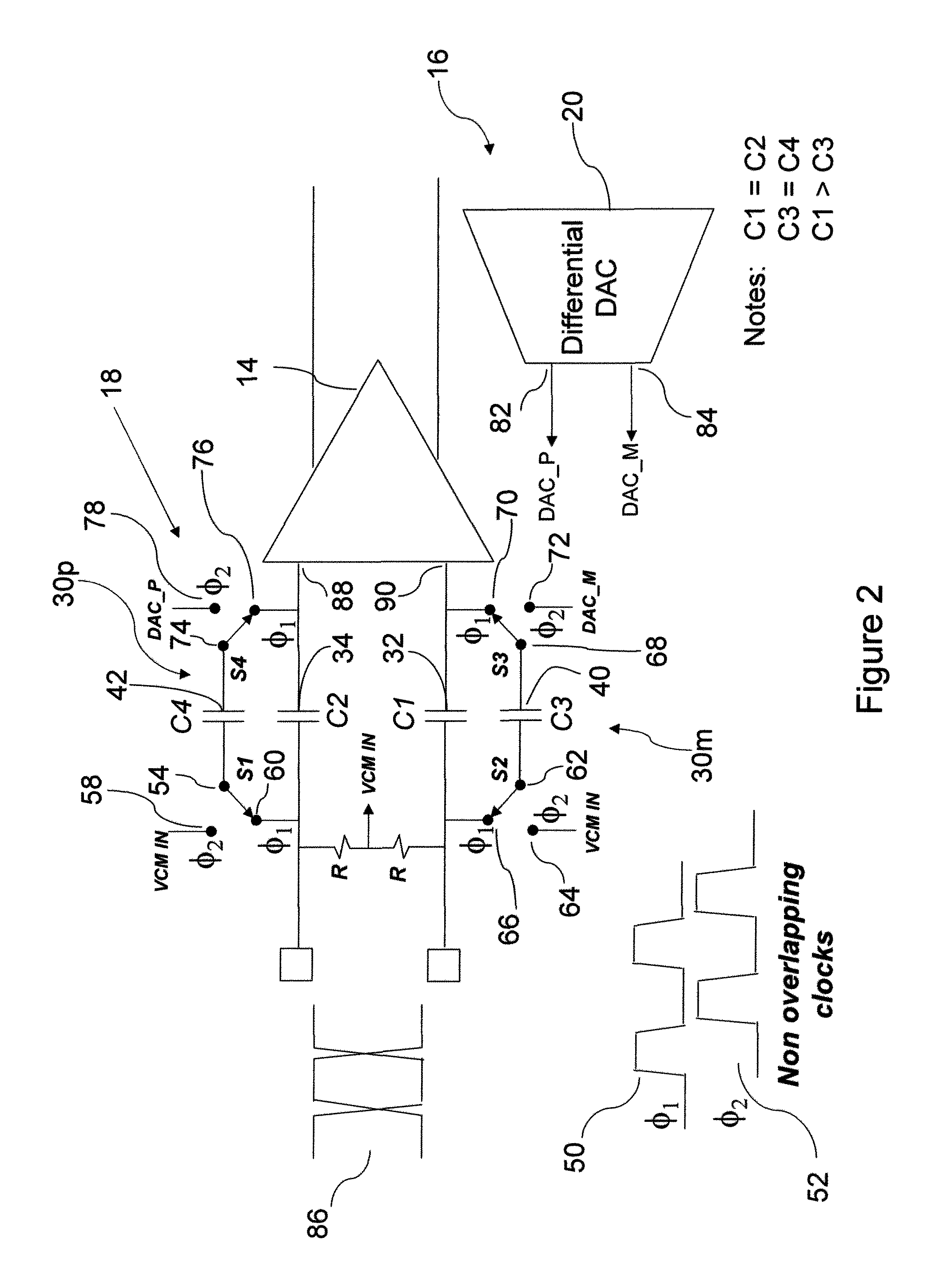
[0023]In broad concept, the subject system and method provide a voltage level shifting circuit interface to preserve operational compatibility between transmitting and receiving integrated circuits. A system realized in accordance with one exemplary embodiment of the present invention employs a switched capacitor technique to translate the DC voltage level of an incoming signal in a controlled manner to a desired level. In the particular example of serial transmission of a signal through differentially paired lines, the system operates to level shift an incoming differential signal's common mode voltage to a desired level, and does so without appreciable attenuation of the signal “riding” on the incoming common mode voltage, or any reduction in the prevailing signal bandwidth.

[0024]In an exemplary embodiment, the system provides a serial interface for high speed differential data transfer between transmitting and receiving integrated circuits which may not otherwise be compatible in...


PUM


Abstract

The serial interface operable, for example, to facilitate high speed differential data transfer between integrated circuits provides level shifting of an incoming data signal using a switched capacitor technique which level shifts the common mode voltage with minimal attenuation and minimal reduction of bandwidths. The serial interface also includes a DC offset correction loop of the input data receiver path. The level shifting circuit operates by sensing the incoming common mode voltage of a differential data signal with a resistor divider and sampling the difference between the measured input common mode voltage and desired input differential voltages generated by a differential DAC in the DC offset correction loop on two small capacitors. The small capacitors are switched across larger in-signal-path capacitors cyclically, so that over time a charge will build up to give the desired level shift to shift the common mode voltage of the incoming signal to the level tolerable by low voltage high speed transistors in the receiving integrated circuit.

Description

BACKGROUND OF THE INVENTION[0001]The present invention is generally directed to a system and method for level translation in a serial data interface. More specifically, the present invention is directed to a system and method for providing voltage level translation in a serial data interface with minimal signal attenuation and bandwidth reduction. The subject system and method provide for translation of common mode voltage to enable safe differential serial data transfer between integrated circuits, even in high speed environments, without adverse effect upon the transferred signal.[0002]With the many advances in the electronics industry, high speed differential serial data transfer between integrated circuits has become commonplace. Many of those same advances, however, require ever more stringent control over various operational parameters, not the least of which is the level of common mode voltage that certain low voltage devices may safely tolerate. Sensitivities to common mode ...

Claims


Application Information

Patent Timeline
Patent Type & Authority Patents(United States)
IPC IPC(8): H03K19/0175H03K5/00G06F7/38
CPCH03K5/003H03M3/494H03K5/249H03K5/2481
Inventor EVANS, WILLIAM PIERCELEUCIUC, ADRIAN
Owner CADENCE DESIGN SYST INC
Learn More