Lens-interchangeable camera body and camera system capable of changing communication method with selected shooting mode
a technology of digital camera and communication method, applied in the field of lenses-interchangeable digital camera systems, can solve the problems of low communication speed and unsuitability for continuous shooting
- Summary
- Abstract
- Description
- Claims
- Application Information
AI Technical Summary
Benefits of technology
Problems solved by technology
Method used
Image
Examples
first embodiment
[0023]A first embodiment of the present invention will now be described in detail with reference to the accompanying drawings.
[0024]The first embodiment concerns a lens-interchangeable, autofocus, single-lens-reflex, digital camera system having selectable shooting modes: a still image shooting mode and a movie shooting mode.
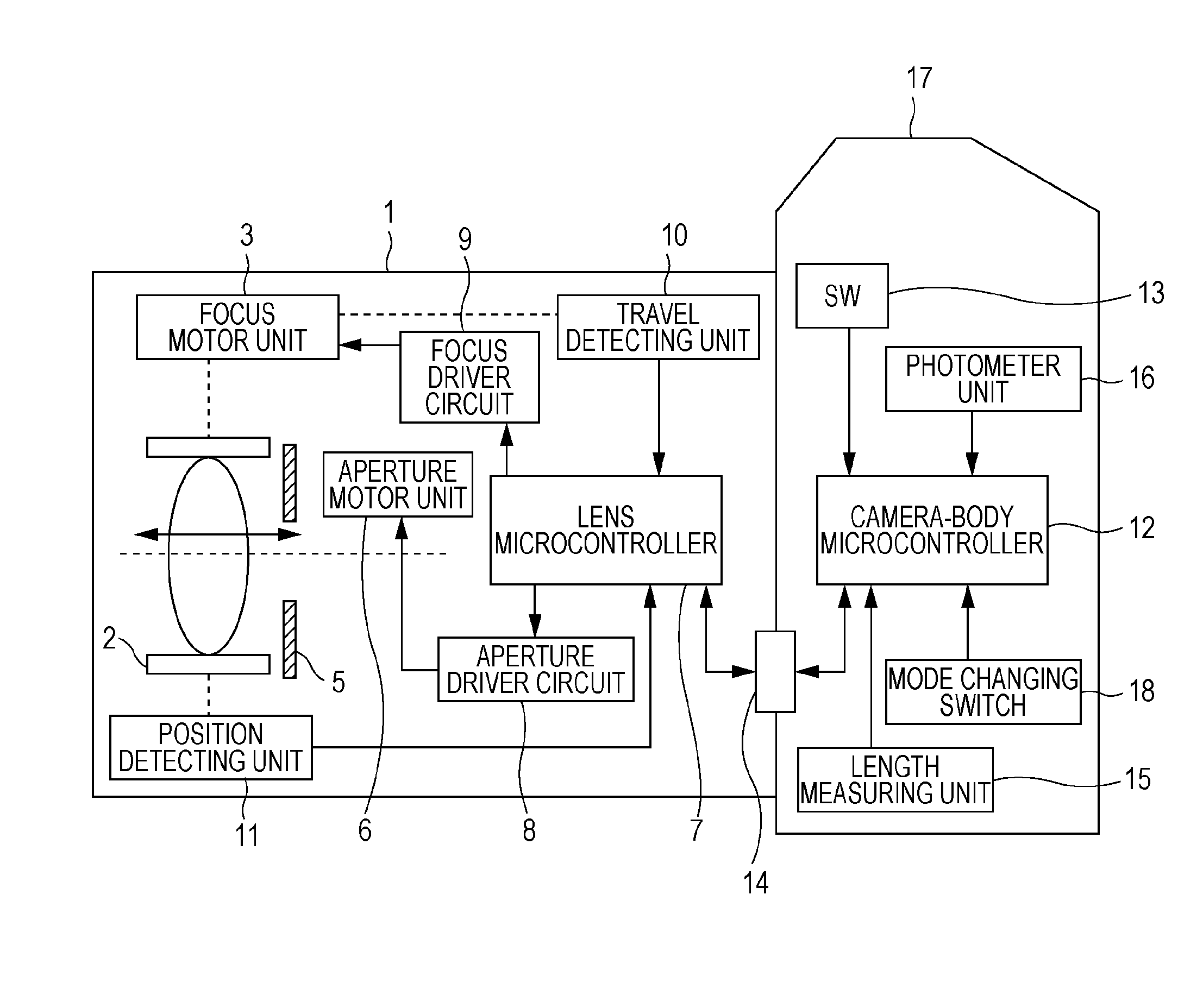
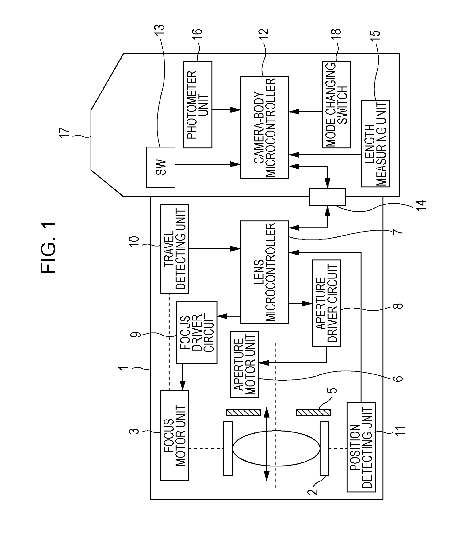
[0025]FIG. 1 is a block diagram showing an interchangeable lens 1 and an autofocus, single-lens-reflex, digital camera body 17. Referring to FIG. 1, communication between and operations of the interchangeable lens 1 and the camera body 17 will first be described.
[0026]A focus lens unit 2 is moved by a focus motor unit 3. The focus motor unit 3 includes a focus motor configured to move the focus lens unit 2, and a series of gears configured to decelerate the focus motor. An aperture unit 5 is moved by an aperture motor unit 6. The aperture motor unit 6 includes an aperture motor configured to move the aperture unit 5, and a series of gears configured to decelerat...
second embodiment
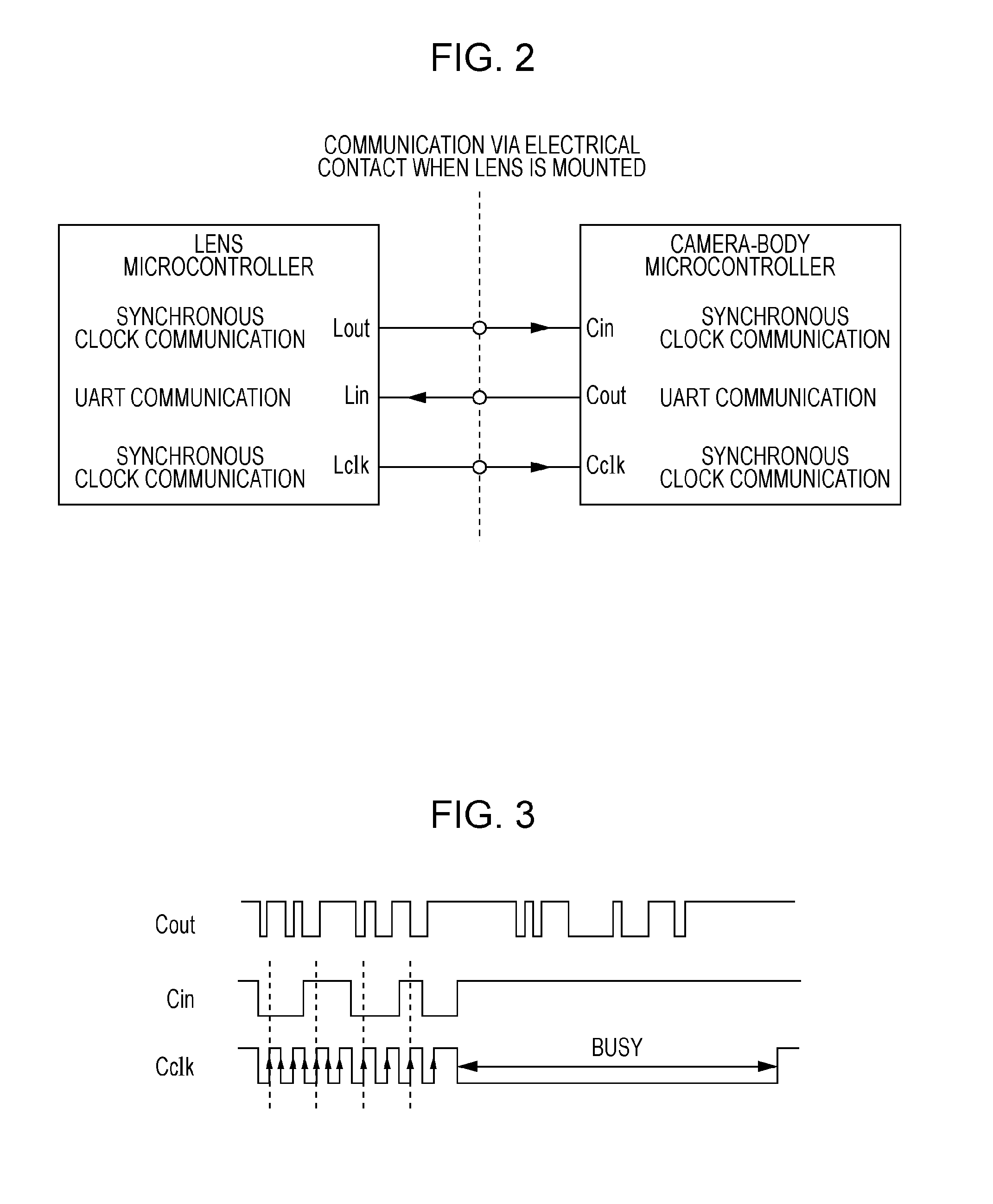
[0039]FIG. 5 shows another exemplary combination of communication methods. In this case, USB communication and UART communication (as the second communication methods) are employed as communication functions provided to the microcontrollers 7 and 12. This combination is employed when the movie shooting mode is selected by using the mode changing switch 18. Communication terminals of the lens microcontroller 7 are shown on the left, and communication terminals of the camera-body microcontroller 12 are shown on the right. The microcontrollers 7 and 12 are connected to each other via the contact point unit 14. The lens microcontroller 7 has a lens data output terminal Lout employing USB communication, a camera-body data input terminal Lin employing USB communication, and an output terminal Lclk employing UART communication. The camera-body microcontroller 12 has a lens data input terminal Cin employing USB communication, a camera-body data output terminal Cout employing USB communicati...
third embodiment
[0040]FIG. 6 shows another exemplary combination of communication methods. In this case, smart card communication and UART communication (as the second communication methods) are employed as communication functions provided to the microcontrollers 7 and 12. Communication terminals of the lens microcontroller 7 are shown on the left, and communication terminals of the camera-body microcontroller 12 are shown on the right. The microcontrollers 7 and 12 are connected to each other via the contact point unit 14. The lens microcontroller 7 has a lens data output terminal Lout employing smart card communication, a camera-body data input terminal Lin employing UART communication, and a spare terminal Lclk. The camera-body microcontroller 12 has a lens data input terminal Cin employing smart card communication, a camera-body data output terminal Cout employing UART communication, and a spare terminal Cclk. Smart card communication is also employed in many recent microcontrollers, and termin...
PUM
 Abstract
Description
Claims
Application Information
 - R&D
- Intellectual Property
- Life Sciences
- Materials
- Tech Scout
- Unparalleled Data Quality
- Higher Quality Content
- 60% Fewer Hallucinations
Browse by: Latest US Patents, China's latest patents, Technical Efficacy Thesaurus, Application Domain, Technology Topic, Popular Technical Reports.
© 2025 PatSnap. All rights reserved.Legal|Privacy policy|Modern Slavery Act Transparency Statement|Sitemap|About US| Contact US: help@patsnap.com


