Switchgear spout design

Active Publication Date: 2014-07-03
EATON INTELLIGENT POWER LIMITED
View PDF13 Cites 12 Cited by
  • Summary
  • Abstract
  • Description
  • Claims
  • Application Information

AI Technical Summary

Benefits of technology

[0009]These needs, and others, are met by at least one embodiment of this invention which provides a spout assembly including a spout and a spout base. The spout base has a cross-sectional area that is smaller than a spout sized to enclose an electrical switching apparatus electrical coupling. That is, the spout base includes a CT support surface with a cross-sectional area that is smaller than the spout cross-sectional area As the current transformers are disposed upon the spout base CT support surface, the current transformers may be constructed with a smaller cross-sectional area, and smaller width, than current transformers sized to be placed upon the spout
[0010]In one exemplary embodiment, the spout assembly includes a spout, a spout base, and a conductor assembly. The spout includes a generally hollow body with

Problems solved by technology

This is a disadvantage, or problem, in that this configuration requires the current transformers to have a greater cross-sectional area than the spout which, in turn, has a greater cross-sectional area tha

Method used


Image

  • Switchgear spout design
  • Switchgear spout design
  • Switchgear spout design

Examples


Embodiment Construction

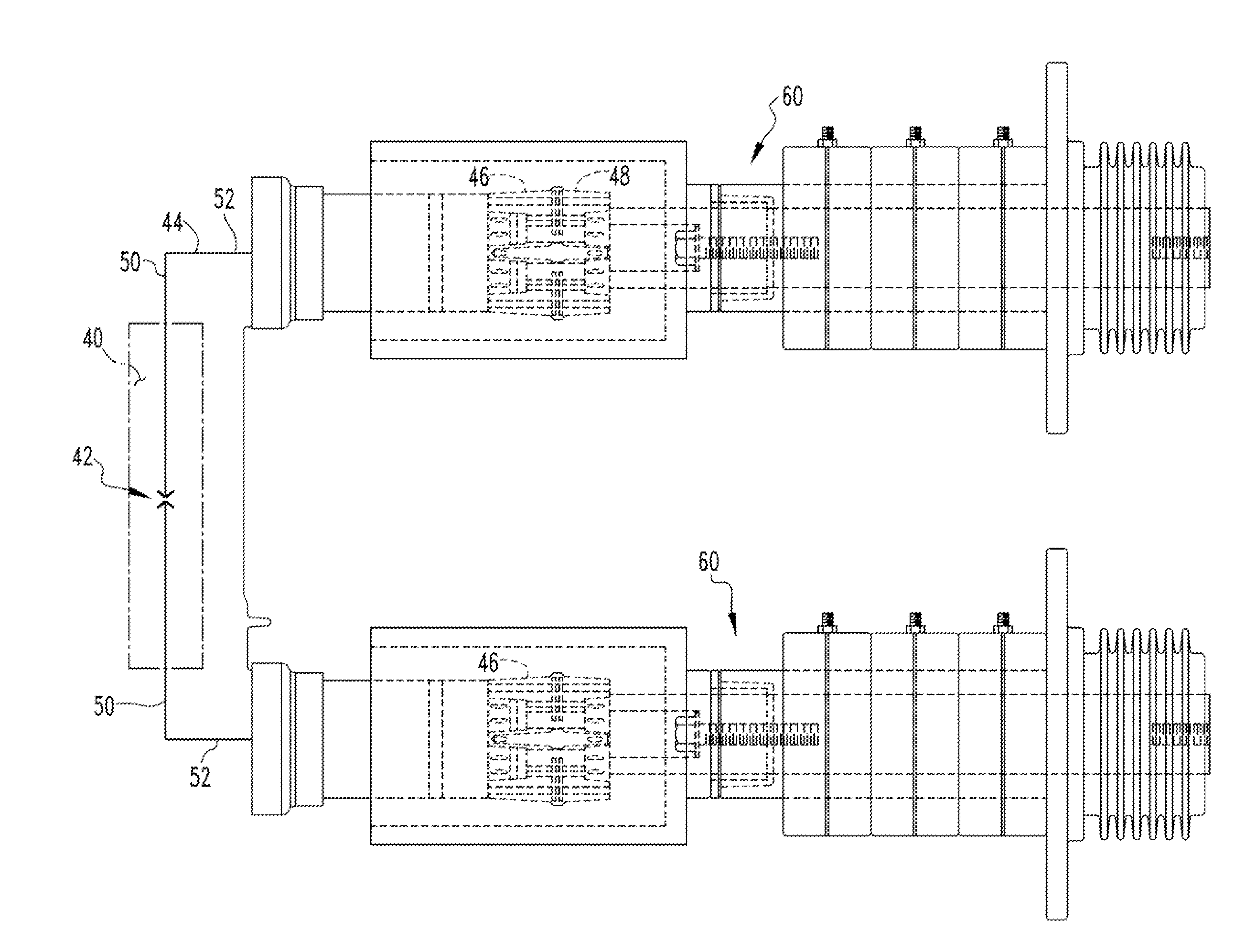
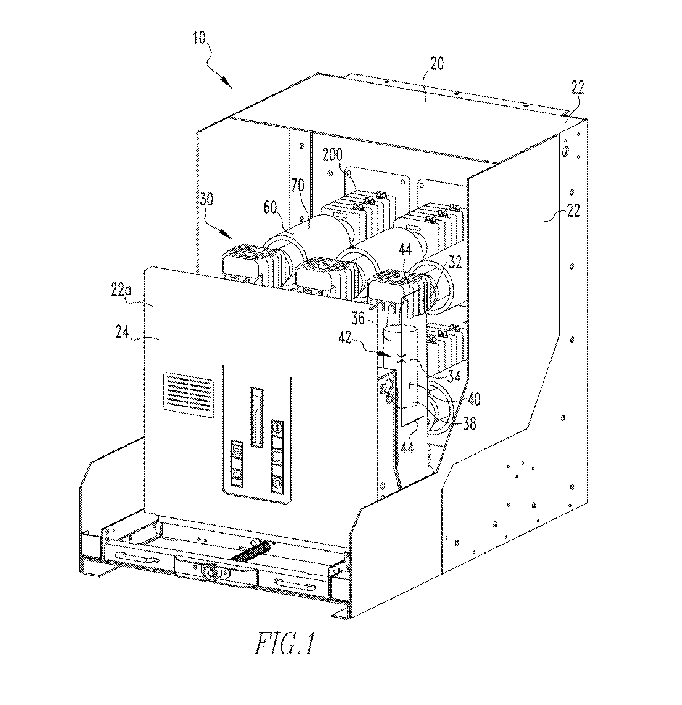
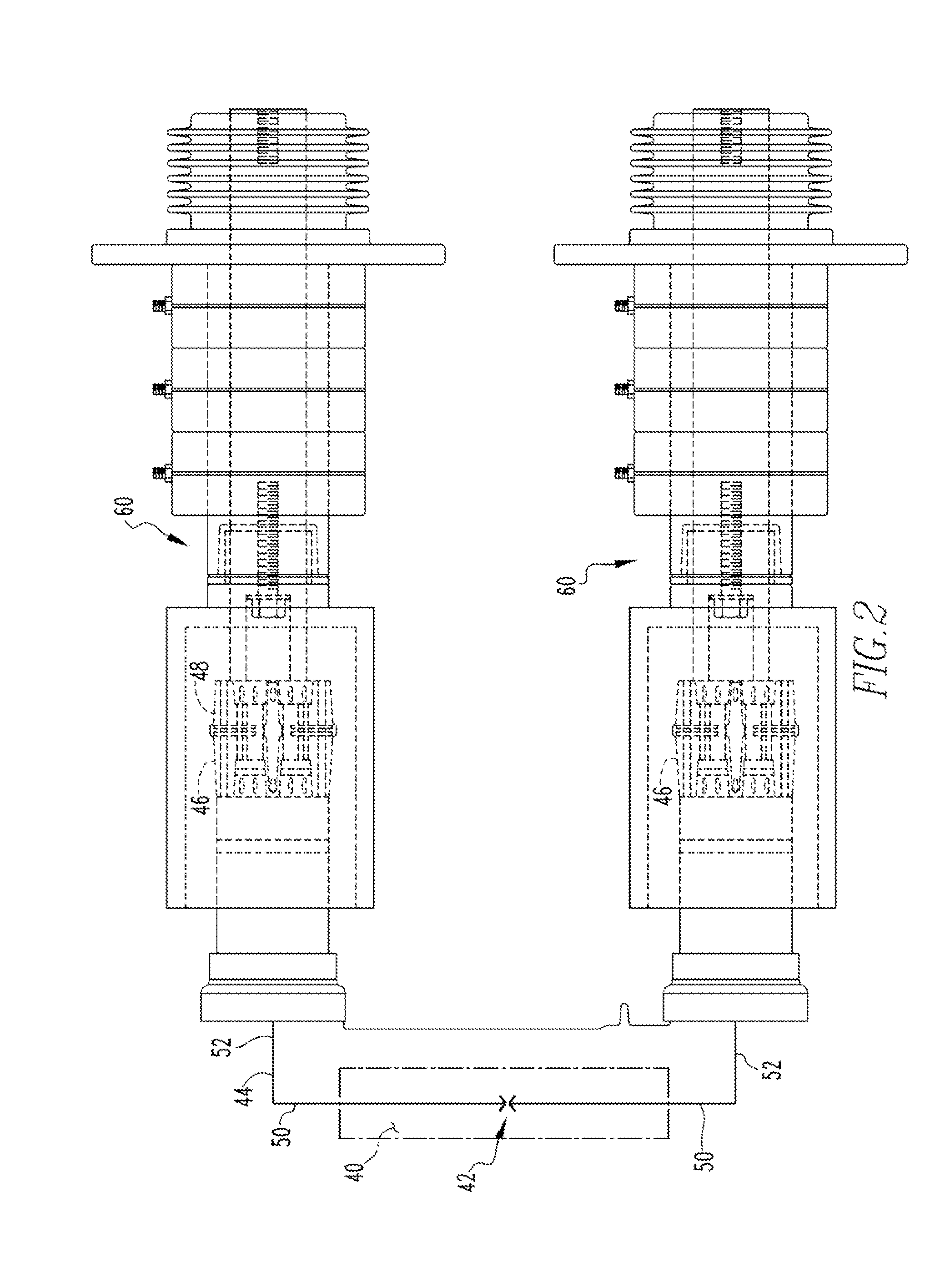
[0016]As used herein, the singular form of “a,”“an,” and “the” include plural references unless the context clearly dictates otherwise. As used herein, the term “number,” or “a number,” shall mean one or an integer greater than one (i.e., a plurality).

[0017]As used herein, the statement that two or more parts or components are “coupled” shall mean that the parts are joined or operate together either directly or indirectly, i.e., through one or more intermediate parts or components, so long as a link occurs. As used herein, “directly coupled” means that two elements are directly in contact with each other. As used herein, “fixedly coupled” or “fixed” means that two components are coupled so as to move as one while maintaining a constant orientation relative to each other. Similarly, two or more elements disposed in a “fixed relationship” means that two components maintain a substantially constant orientation relative to each other.

[0018]As used herein, the word “unitary” means a comp...


PUM


Abstract

A spout assembly is provided. The spout assembly includes a spout and a spout base. The spout base has a cross-sectional area that is smaller than a spout sized to enclose an electrical switching apparatus electrical coupling. That is, the spout base includes a CT support surface with a cross-sectional area that is smaller than the spout cross-sectional area. Current transformers are disposed upon the spout base CT support surface.

Description

BACKGROUND OF THE INVENTION[0001]1. Field of the Invention[0002]The disclosed concept relates to a switchgear spout that supports current transformers.[0003]2. Background Information[0004]Switchgear devices (e.g., without limitation, electrical switching apparatus, such as circuit switching devices and circuit interrupters such as circuit breakers, contactors, motor starters, motor controllers and other load controllers), are, typically, removably mounted in an electrical enclosure. That is, the switchgear device includes a housing assembly and an electrical switching apparatus. The switchgear device housing assembly defines an enclosure sized to enclose the electrical switching apparatus. Users prefer the switchgear housing assembly enclosure to have a minimal width. Users, however, have a greater tolerance for deeper (front to back) switchgear housing assembly enclosures.[0005]For the sake of an example, hereinafter the switching device is described as a vacuum circuit interrupter...

Claims


Application Information

Patent Timeline
IPC IPC(8): H02B13/00H05K5/02
CPCH05K5/0217H02B13/00H02B11/04
Inventor SMITH, JAMES E.LECCIA, BRAD ROBERTCHEN, STEVEN Z.
Owner EATON INTELLIGENT POWER LIMITED
Why Eureka
Try Eureka