
Methods and Systems for Enhanced Automated Visual Inspection of a Physical Asset

a technology of automated visual inspection and physical asset, applied in the field of computer-implemented programs, can solve the problems of complex physical asset disassembly or service, time-consuming overlaying, comparison, matching, etc., and achieve the effect of reducing the complexity of known methods and systems of visual inspection

Active Publication Date: 2014-07-03
GENERAL ELECTRIC CO
View PDF17 Cites 27 Cited by
  • Summary
  • Abstract
  • Description
  • Claims
  • Application Information

AI Technical Summary

Benefits of technology

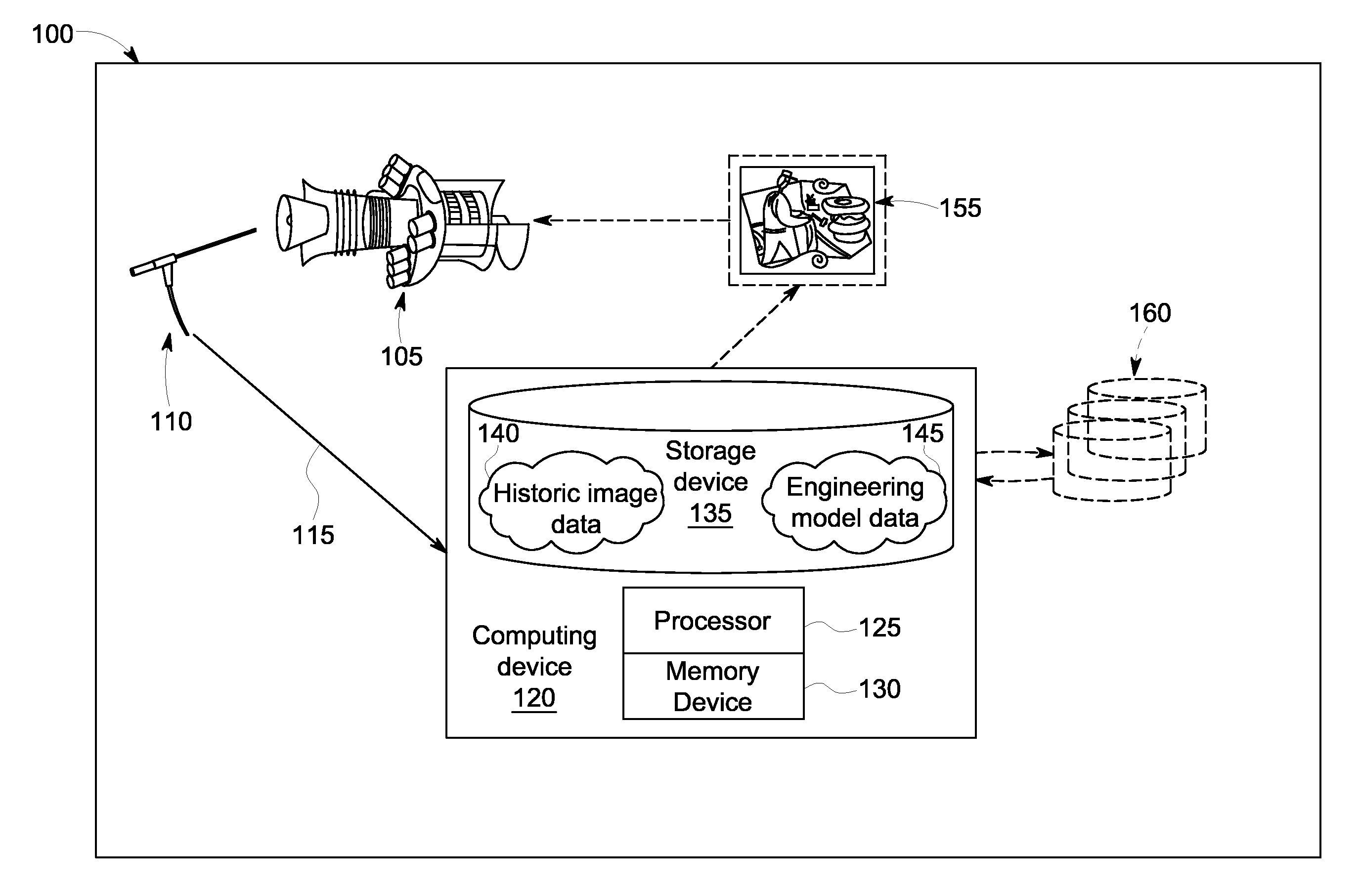
This patent describes a system and method for inspecting physical assets using a visual inspection device and an engineering model. The system can capture images of the physical asset and compare them to historic images to find matching ones. It can also identify matching engineering models that match the captured images. This allows for more efficient and automated inspection of physical assets, reducing the need for human labor.

Problems solved by technology

In some such known cases, disassembly or servicing of complex physical assets may take hours to perform.
Such overlaying, comparison, and matching may be very time consuming.
Known methods and systems of visual inspection may also face the complexity that when visual data is received by the human technician, it is often too late to obtain new physical measurements that have not been previously collected by field engineers.
Such known methods and systems of visual inspection of physical assets using optical devices do not facilitate efficient and effective identification of the component corresponding to visual data sent from the optical device to the human technician.
Review of the architectural details of each component and sub-component is often a necessary and time-consuming aspect of using known methods of visual inspection.
Misidentification may be logistically and financially expensive.

Method used


Image

  • Methods and Systems for Enhanced Automated Visual Inspection of a Physical Asset
  • Methods and Systems for Enhanced Automated Visual Inspection of a Physical Asset
  • Methods and Systems for Enhanced Automated Visual Inspection of a Physical Asset

Examples


Embodiment Construction

[0014]In the following specification and the claims, reference will be made to a number of terms, which shall be defined to have the following meanings

[0015]The singular forms “a”, “an”, and “the” include plural references unless the context clearly dictates otherwise.

[0016]“Optional” or “optionally” means that the subsequently described event or circumstance may or may not occur, and that the description includes instances where the event occurs and instances where it does not.

[0017]As used herein, the term “non-transitory computer-readable media” is intended to be representative of any tangible computer-based device implemented in any method or technology for short-term and long-term storage of information, such as, computer-readable instructions, data structures, program modules and sub-modules, or other data in any device. Therefore, the methods described herein may be encoded as executable instructions embodied in a tangible, non-transitory, computer readable medium, including,...


PUM


Abstract

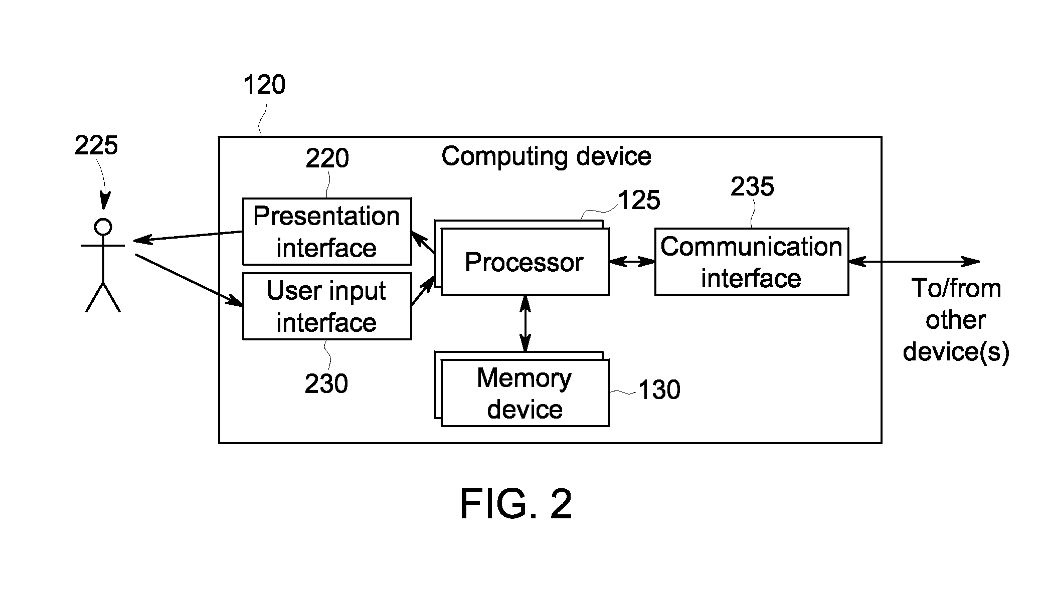
A computer-implemented system for enhanced automated visual inspection of a physical asset includes a visual inspection device capable of generating images of the physical asset and a computing device including a processor and a memory device coupled to the processor. The computing device includes a storage device coupled to the memory device and coupled to the processor. The storage device includes at least one historic image of the physical asset and at least one engineering model substantially representing the physical asset. The computing device is configured to receive, from a present image source, at least one present image of the physical asset captured by the visual inspection device. The computing device is configured to identify at least one matching historic image corresponding to the at least one present image. The computing device is configured to identify at least one matching engineering model corresponding to the at least one present image.

Description

BACKGROUND[0001]The field of the invention relates generally to computer-implemented programs and, more particularly, to a computer-implemented system for enhanced automated visual inspection of a physical asset.[0002]Known methods of visual inspection of physical assets include the use of optical devices inserted within such physical assets without human entrance. Such known methods provide benefits by allowing for rapid visual analysis of complex physical assets that may be inaccessible to human technicians without disassembly or other servicing. In some such known cases, disassembly or servicing of complex physical assets may take hours to perform. During such disassembly or servicing, many such complex physical assets must be rendered temporarily inoperable. Therefore, known methods of visual inspection rapidly expedite analysis of internal conditions of complex physical assets and reduce downtime that may be caused by disassembly or servicing.[0003]Known methods and systems of ...

Claims


Application Information

Patent Timeline
IPC IPC(8): G06T7/00
CPCG06T7/0002G06T2207/30164G06T2207/30244G06T7/33G06F16/583G06T7/001
Inventor LIM, SER NAMKUMAR, VINOD PADMANABHANIRVING, RUSSELL ROBERTLAFLEN, JOHN BRANDONGUAN, LILIU, SHUBAOYANG, XINGWEI
Owner GENERAL ELECTRIC CO
Learn More