
Spatially Diverse Antennas for a Headset Computer

a technology of diverse antennas and headset computers, applied in the field of satellite-based diverse antennas for headset computers, can solve problems such as inefficiency, and achieve the effect of reducing rf losses

Active Publication Date: 2014-07-03
KOPIN CORPORATION
View PDF11 Cites 35 Cited by
  • Summary
  • Abstract
  • Description
  • Claims
  • Application Information

AI Technical Summary

Benefits of technology

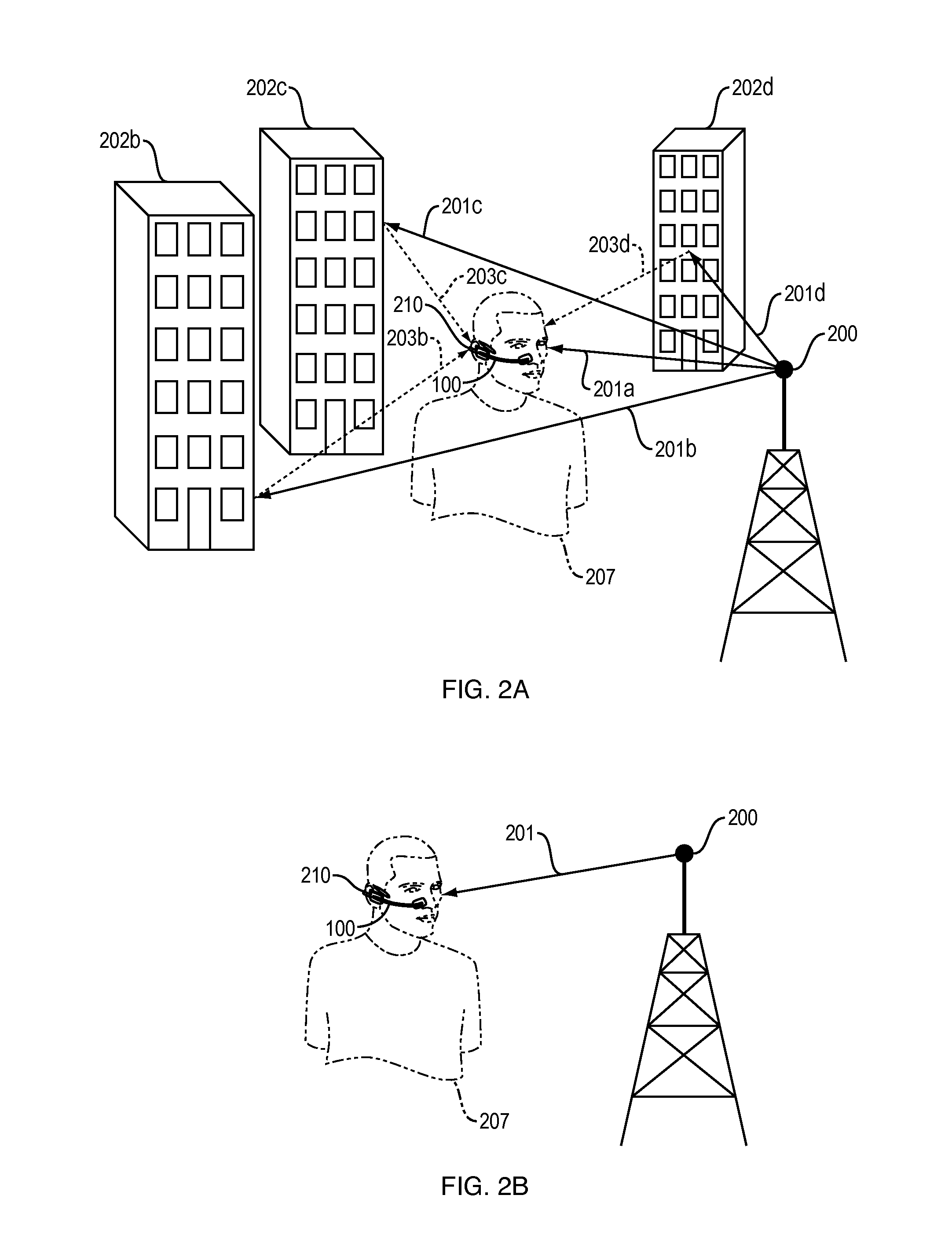
The patent text describes a headset computing device that includes RF switches to switch between multiple antennas. This results in more robust communication links and reduced RF losses compared to using a splitter / combiner. The RF switches are connected to an RF transceiver for receiving and transmitting RF signals through the selected antenna. The technical effect is improved communication performance using a headset computing device.

Problems solved by technology

Typically, an antenna element also radiates at odd multiples of a quarter wavelength of its fundamental resonant frequency, although not as efficiently as at its fundamental resonant frequency.
Also, omnidirectional antennas are typically used at lower frequency where a directional antenna would be too large and too expensive or where a directional antenna is simply not required.

Method used


Image

  • Spatially Diverse Antennas for a Headset Computer
  • Spatially Diverse Antennas for a Headset Computer
  • Spatially Diverse Antennas for a Headset Computer

Examples


Embodiment Construction

[0033]A description of example embodiments of the invention follows.

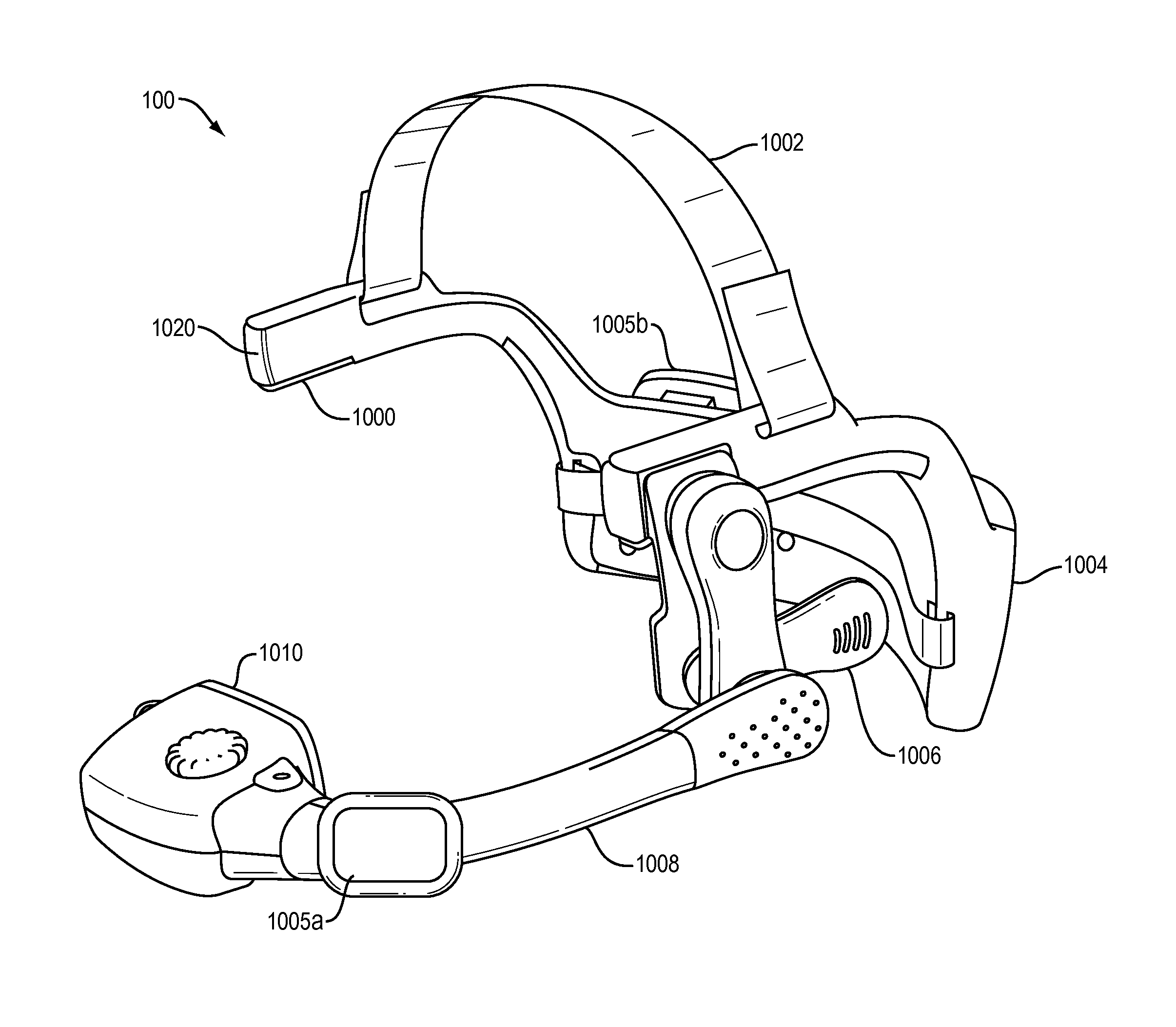
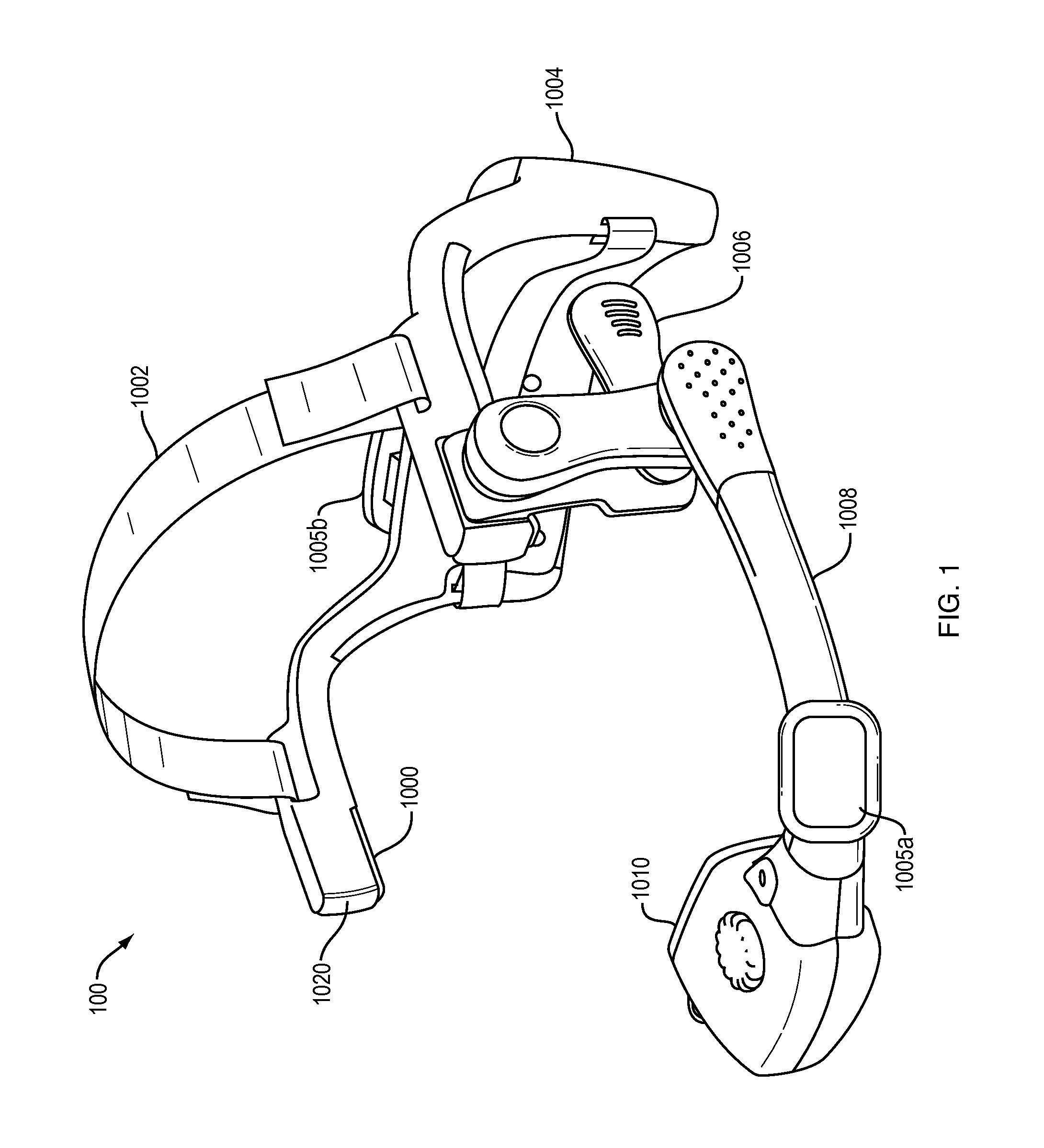
[0034]The present application relates to wireless communications and more particularly to a wireless computing headset with one or more micro-display devices and spatially diverse antennas.

[0035]Mobile computing devices, such as notebook PC's, smart phones, and tablet computing devices, are now common tools used for producing, analyzing, communicating, and consuming data in both business and personal life. Consumers continue to embrace a mobile digital lifestyle as the ease of access to digital information increases with high-speed wireless communications technologies becoming ubiquitous. Popular uses of mobile computing devices include displaying large amounts of high-resolution computer graphics information and video content, often wirelessly streamed to the device. While these devices typically include a display screen, the preferred visual experience of a high-resolution, large format display cannot be easily re...


PUM


Abstract

The invention presented relates to wireless handsfree head worn headset computing devices including a microdisplay device and spatially diverse antenna system. The spatially diverse antenna system provides an effective headset computing device radiation pattern that enables arbitrary user movement and promotes freedom of mobility. Disclosed is a headset computing device including a head worn frame having a profile relatively low in height with respect to a user's head, the user's head creating a RF shadow region along the headset profile by blocking line-of-sight RF propagation paths, the headset includes two or more antennas integrated with the headset frame to sufficiently maintained its low profile. Each antenna has a radiation pattern and are collectively arranged to form an omnidirectional radiation pattern, where at least a first radiation pattern provides coverage in the line-of-sight propagation path while the at least second radiation antenna pattern is in the RF shadow region.

Description

RELATED APPLICATION[0001]This application claims the benefit of U.S. Provisional Application No. 61 / 747,191, filed on Dec. 28, 2012. The entire teachings of the above application(s) are incorporated herein by reference.BACKGROUND OF THE INVENTION[0002]Wireless communication is the transfer of information between two or more points that are not connected by an electrical conductor. Most common wireless communication technologies, such as radio, use electromagnetic waves typically in the radio frequency (RF) ranges. Information, such as sound, video, or other data, is transmitted by systematically modulating at least some property of a RF carrier. Modulation techniques are well known and in general include modulating the amplitude, frequency, or phase of the RF carrier.[0003]Wireless communication is generally achieved through the following process. A source generates a message that when represented in an electrical waveform is referred to as a baseband signal. A transmitter modulates...

Claims


Application Information

Patent Timeline
Patent Type & Authority Applications(United States)
IPC IPC(8): H01Q1/27H04M1/05
CPCH04M1/05H01Q1/273H01Q3/24H01Q9/42H01Q21/24H01Q25/005H04B1/385
Inventor FERGUSON, DAVID B.
Owner KOPIN CORPORATION
Learn More