Liquid ejection head and liquid ejection apparatus

Inactive Publication Date: 2014-07-10
CANON KK
View PDF2 Cites 6 Cited by
  • Summary
  • Abstract
  • Description
  • Claims
  • Application Information

AI Technical Summary

Benefits of technology

[0010]The exothermic energy amount caused by a dielectric loss increases in proportion to the square of an applied voltage and increases in proportion to the frequency. In the case of ejecting high-viscosity liquid, it is necessary to supply a piezoelectric

Problems solved by technology

The heat generated by the piezoelectric element may degrade electric characteristics of the piezoelectric element and ink characteristics.
Therefore, if the t

Method used


Image

  • Liquid ejection head and liquid ejection apparatus
  • Liquid ejection head and liquid ejection apparatus
  • Liquid ejection head and liquid ejection apparatus

Examples


first embodiment

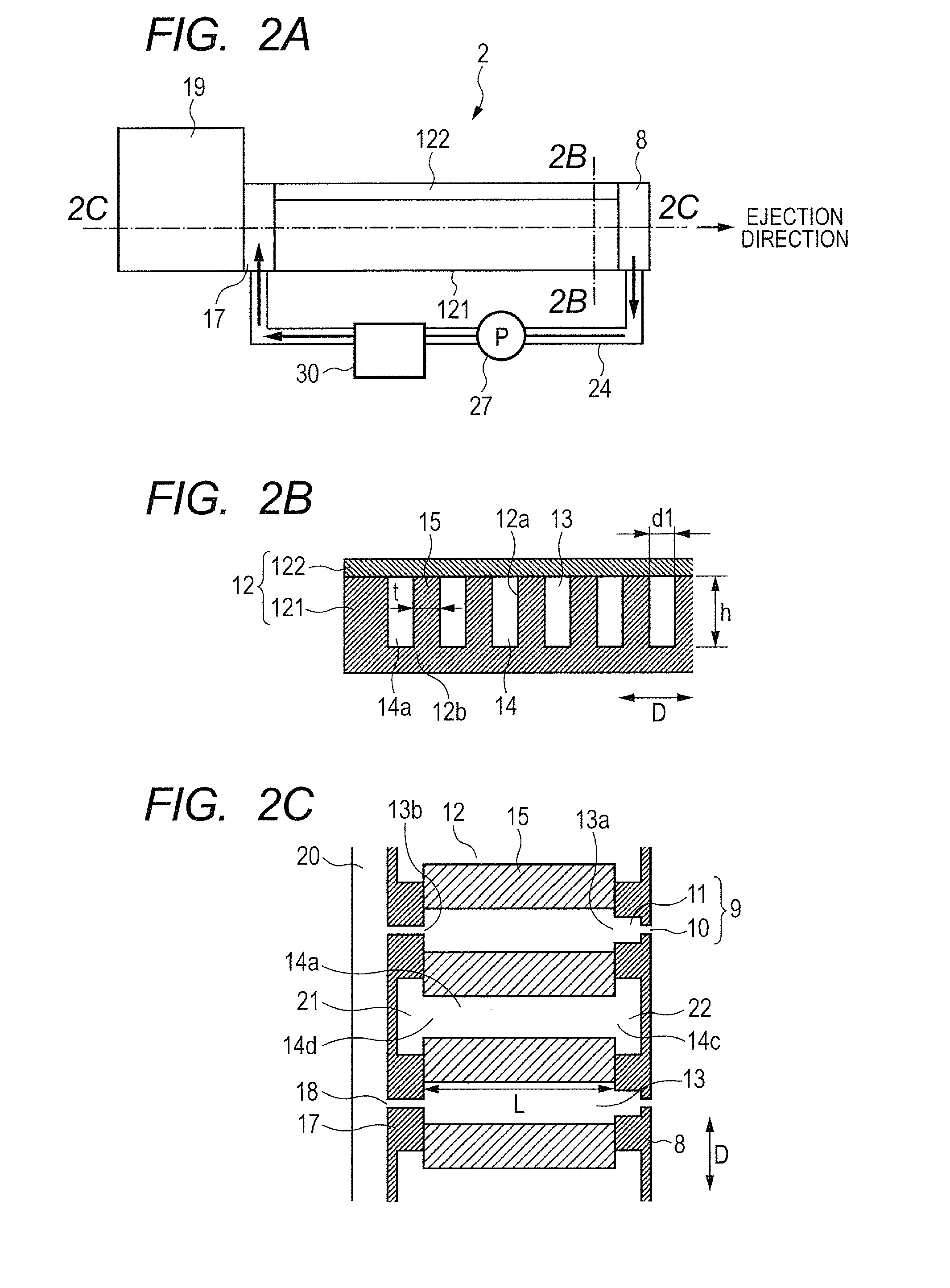
[0038]FIGS. 2A to 7 illustrate a liquid ejection head according to a first embodiment of the present invention. FIG. 2A is a side view of the liquid ejection head. FIG. 2B is a cross-sectional view of the liquid ejection head taken alone line 2B-2B of FIG. 2A. FIG. 2C is a cross-sectional view of the liquid ejection head taken along line 2C-2C of FIG. 2A. FIG. 3 is an exploded perspective view illustrating each member forming the liquid ejection head 2 three-dimensionally.

[0039]As illustrated in FIG. 2B, the liquid ejection head 2 includes a piezoelectric member 12. The piezoelectric member 12 includes a main body 121 formed of a piezoelectric body and a cover plate 122. In the piezoelectric member 12, a pressure chamber 13 which communicates with each ejection orifice 10 and holds liquid to be ejected from each ejection orifice 10 and a first temperature control liquid flow path 14a in which a first temperature control liquid flows are formed alternately in a direction D orthogonal...

second embodiment

[0060]Next, a second embodiment of the present invention is described. In the following, the descriptions of the components which are common to those of the first embodiment are omitted. FIG. 7 is an exploded perspective view of a liquid ejection head 2 according to this embodiment.

[0061]In the liquid ejection head 2 of this embodiment, a nozzle plate side intermediate plate 32 is provided between a piezoelectric member 12 and a nozzle plate 8. In the nozzle plate side intermediate plate 32, a first outlet side flow path 22 is formed in a groove shape, and the first outlet side flow path 22 extends to the side surface of the nozzle plate side intermediate plate 32 along the nozzle plate side intermediate plate 32. The nozzle plate side intermediate plate 32 also includes a widening portion 11 which communicates with a pressure chamber 13 and an ejection orifice 10 and has a flow path cross section larger than the ejection orifice 10. In one example, the nozzle plate side intermediat...

third embodiment

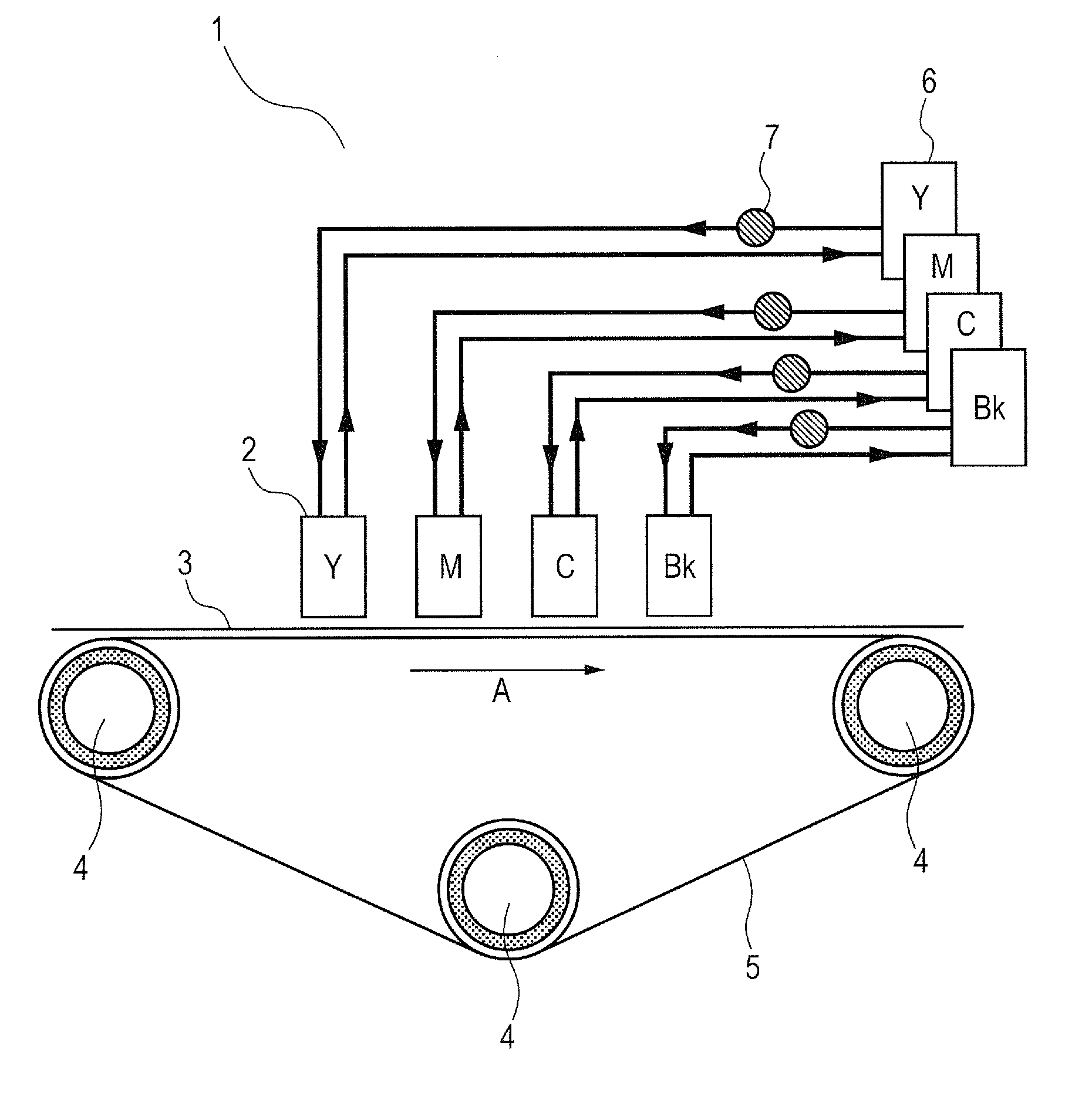
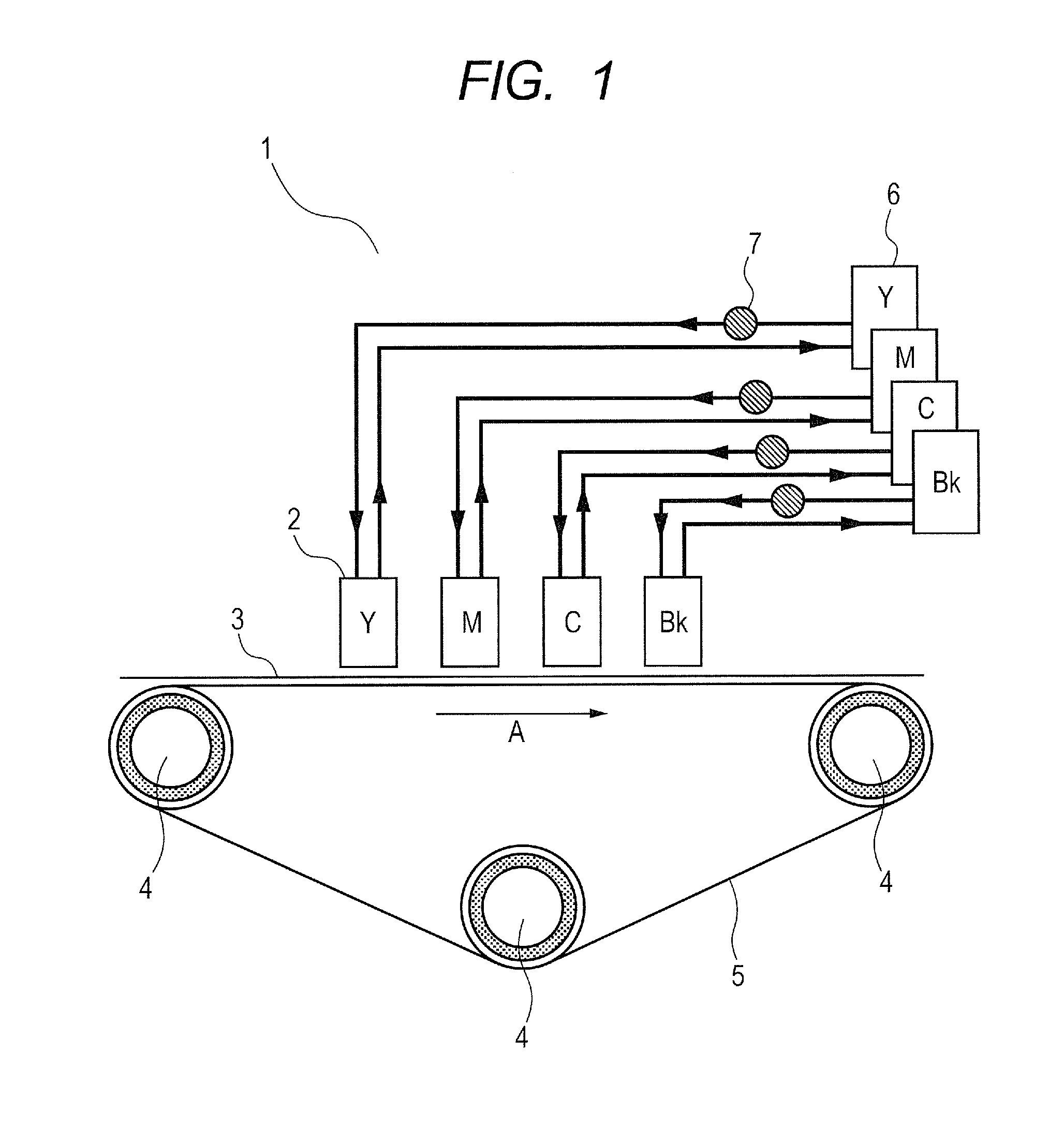
[0065]Next, a third embodiment of the present invention is described. In the following, the descriptions of the components which are common to those of the first and second embodiments are omitted. FIG. 8 is a schematic structural view of a liquid ejection apparatus 1 of this embodiment, and FIG. 9 is an exploded perspective view illustrating each member constituting a liquid ejection head 2 three-dimensionally.

[0066]In this embodiment, nozzles 9 are placed two-dimensionally. Specifically, multiple nozzle arrays (ejection orifice arrays) 43 are provided in a nozzle plate 8, and each nozzle array 43 includes multiple nozzles 9 arranged in a direction D orthogonal to a recording medium conveyance direction A. The nozzle arrays 43 are placed at an interval in the recording medium conveyance direction A and shifted from each other in the direction D orthogonal to the recording medium conveyance direction A. Due to such an arrangement of the nozzles 9 (ejection orifices), an effective no...


PUM


Abstract

Provided is a liquid ejection head, including a pressure chamber in which a liquid flows, at least a part of a wall surface of the pressure chamber being formed of a piezoelectric member; an ejection orifice for ejecting the liquid in the pressure chamber pressurized by deformation of the piezoelectric member; a temperature control liquid flow path in which a temperature control liquid flows, the temperature control liquid flow path being provided independently from the pressure chamber and formed so as to be adjacent to the pressure chamber via the wall surface of the pressure chamber, at least a part of a wall surface of the temperature control liquid flow path being formed of the piezoelectric member; and a circulation liquid flow path communicating with the temperature control liquid flow path, for circulating the temperature control liquid.

Description

TECHNICAL FIELD[0001]The present invention relates to a configuration for controlling a temperature of a liquid ejection head for ejecting liquid by a piezoelectric element.BACKGROUND ART[0002]Various proposals have been made regarding a liquid ejection head to be mounted on a liquid ejection apparatus typified by an ink-jet recording apparatus. Of those, a liquid ejection head using a piezoelectric element as a source for generating liquid ejection energy has an advantage of being capable of handling any kind of liquid (ink) to be ejected.[0003]In recent years, an attempt has been made to use an ink-jet recording apparatus for commercial printing such as print on demand (POD), and there is a demand for an increase in printing speed. For this purpose, it is requested that the drive frequency of a liquid ejection head be enhanced.[0004]On the other hand, in order to reduce deformation (curling, cockling, etc.) of a recording medium caused by water contained in ink to be ejected from ...

Claims


Application Information

Patent Timeline
IPC IPC(8): B05B17/00
CPCB05B17/0646B41J2/14209B41J2/14233B41J2202/08
Inventor SASAGAWA, NAOTOKITAKAMI, KOICHI
Owner CANON KK
Why Eureka
Try Eureka