Apparatus and method for displaying hologram image

Inactive Publication Date: 2014-07-10
ELECTRONICS & TELECOMM RES INST
View PDF4 Cites 11 Cited by
  • Summary
  • Abstract
  • Description
  • Claims
  • Application Information

AI Technical Summary

Benefits of technology

This patent describes an apparatus and method for displaying hologram images using a user image, a reflection hologram image, and a hologram creator to create the display hologram image based on the position of the pupil of the user. The light source provider controls the position of the light source to match the position of the pupil, and the hologram display unit displays the display hologram image using a light condensing unit. The technical effects include improved image quality and accuracy of hologram display.

Problems solved by technology

In the case of a stereoscopic display using a general stereo matching technology, a mismatch may occur between a focal convergence angle and focus accommodation information.
Accordingly, correspondence information between a gazing point of the user and a convergence focus in the case of viewing a 3D object in the real world may not match correspondence information between a gazing point of a user and a convergence focus in the case of viewing the 3D object through an autostereoscopic display.
Mismatching correspondence information may aggravate the confusion of the user, and may cause discomfort and fatigues of eyes.
However, many LCDs currently commercialized have a pixel pitch of 100 μm or more and thus, may have a narrow viewing window with which a user may view using only a single pupil of the user due to a very small diffraction angle.
However, due to an error in tracking a position of a pupil of a user that occurs in the case of calculating the position of the pupil based on a 3D position of the pupil, an error in controlling a position of a light source that occurs in the case of locating the light source at the position of the pupil, aberration of an optical condensing lens, and the like, the position of the pupil of the user and the position of the viewing window may mismatch.
Accordingly, the user may have difficulty in clearly observing a 3D image reproduced through a hologram.
In the case of the error in tracking the position of the pupil of the user, it may be possible to increase accuracy of the position of the pupil by enhancing resolution of a pupil image, but there are some constraints in increasing the accuracy.
However, in terms of techniques and costs, it is difficult to develop the LCD SLM with a small pixel pitch sufficient to obtain a satisfactory viewing window.
Further, in terms of costs or physical respect, there are some constraints in decreasing the error in controlling the position of the light source or aberration of an optical condensing lens, which is another factor that causes mismatch between the position of the pupil of the user and the position of the viewing window.
The image analyzer may analyze a center position error between a center position of the viewing window and a center position of the pupil of the user that is analyzed from the reflection hologram image, and may transmit the analyzed center position error to the light source provider.

Method used


Image

  • Apparatus and method for displaying hologram image
  • Apparatus and method for displaying hologram image
  • Apparatus and method for displaying hologram image

Examples


Embodiment Construction

[0034]Reference will now be made in detail to exemplary embodiments of the present invention, examples of which are illustrated in the accompanying drawings, wherein like reference numerals refer to like elements throughout. Exemplary embodiments are described below to explain the present invention by referring to the figures.

[0035]When it is determined detailed description related to a related known function or configuration they may make the purpose of the present invention unnecessarily ambiguous in describing the present invention, the detailed description will be omitted here. Also, terminologies used herein are defined to appropriately describe the exemplary embodiments of the present invention and thus may be changed depending on a user, the intent of an operator, or a custom. Accordingly, the terminologies must be defined based on the following overall description of this specification.

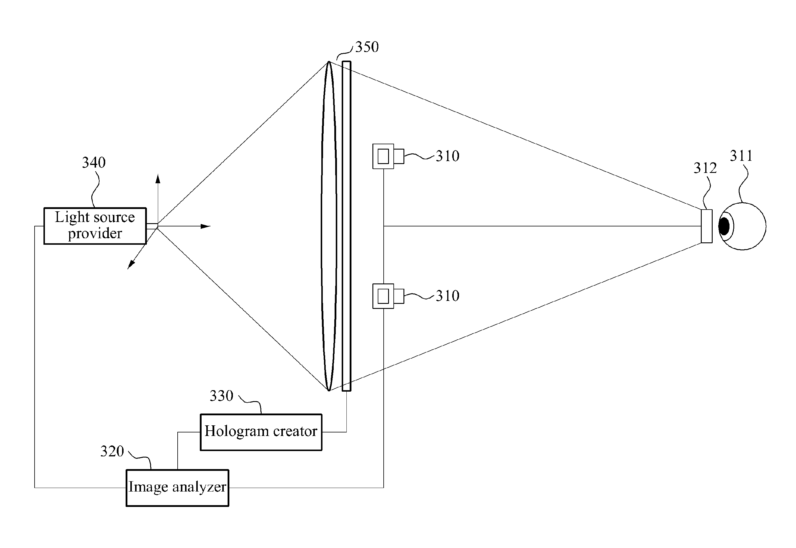
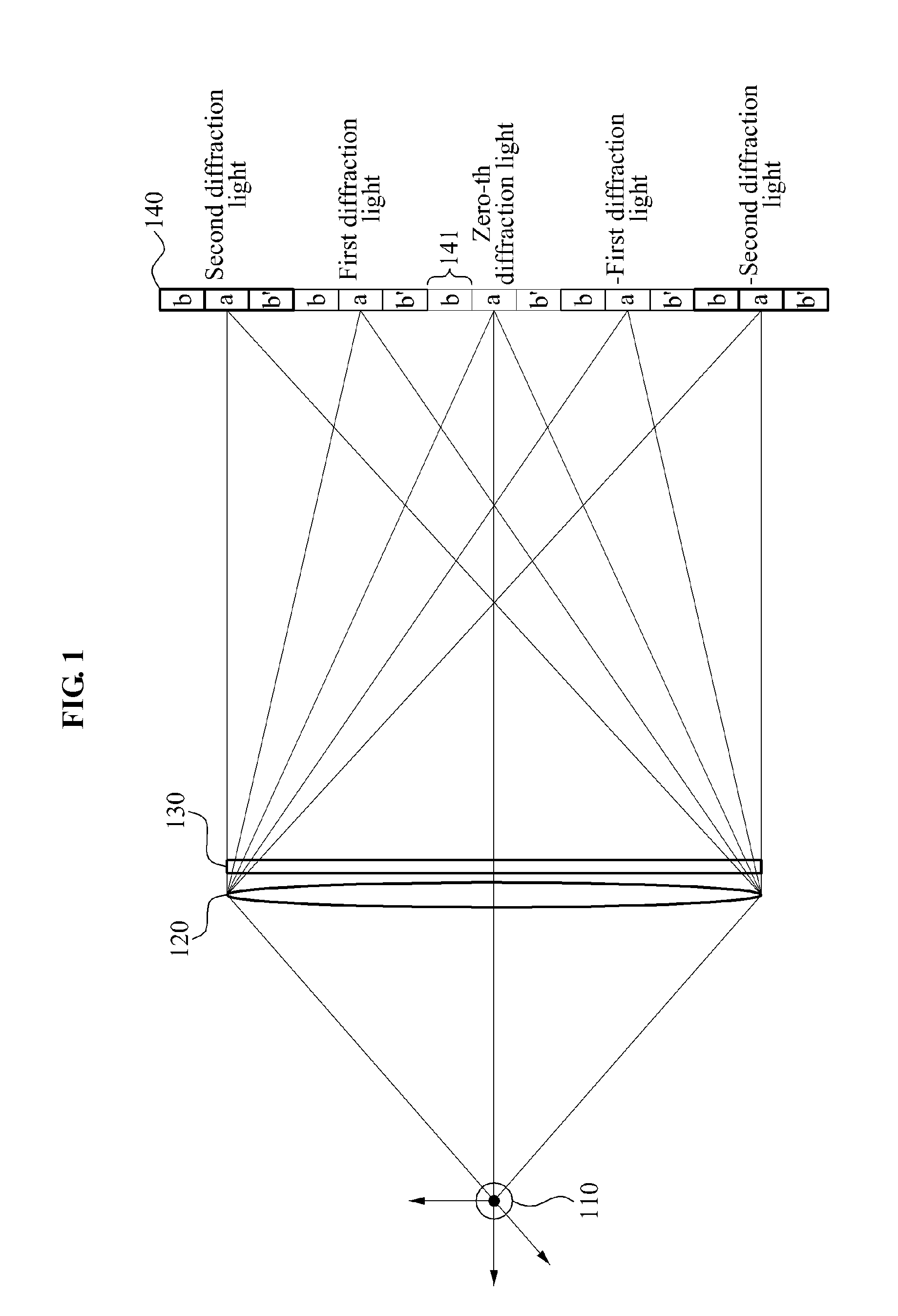
[0036]FIG. 1 is a diagram illustrating an example of a holographic display according to an...


PUM


Abstract

Provided is an apparatus and method for displaying a hologram image that may display a hologram image created by tracking a position of a pupil of a user using an acquired user image, tracking a position of a light source of a reflection hologram image that is reflected from appearance of the user, and by correcting a position of a light source of a display hologram image based on the position of the pupil of the user.

Description

CROSS-REFERENCE TO RELATED APPLICATION[0001]This application claims the priority benefit of Korean Patent Application No. 10-2013-0002953, filed on Jan. 10, 2013, in the Korean Intellectual Property Office, the disclosure of which is incorporated herein by reference.BACKGROUND[0002]1. Field of the Invention[0003]Embodiments of the present invention relate to a hologram image displaying apparatus and method that may match a position of a hologram viewing window and a position of a pupil of a user.[0004]2. Description of the Related Art[0005]In the case of a stereoscopic display using a general stereo matching technology, a mismatch may occur between a focal convergence angle and focus accommodation information. Here, the focal convergence angle is used to rotate pupils of both eyes toward the middle of the forehead to be focused on a feature point of a three-dimensional (3D) object, and the focus accommodation information is used to adjust a thickness of a crystalline lens that serve...

Claims


Application Information

Patent Timeline
IPC IPC(8): G03H1/04H04N13/04
CPCH04N13/0484G03H1/0443G03H1/2286G03H1/2294G03H2001/2236G03H2001/2292G03H2226/05G03H2227/03H04N13/383G03H1/04
Inventor PARK, MIN SIKMOON, KYUNG AEKIM, JIN WOONG
Owner ELECTRONICS & TELECOMM RES INST
Why Eureka
Try Eureka