Optical system and image projection apparatus including the same
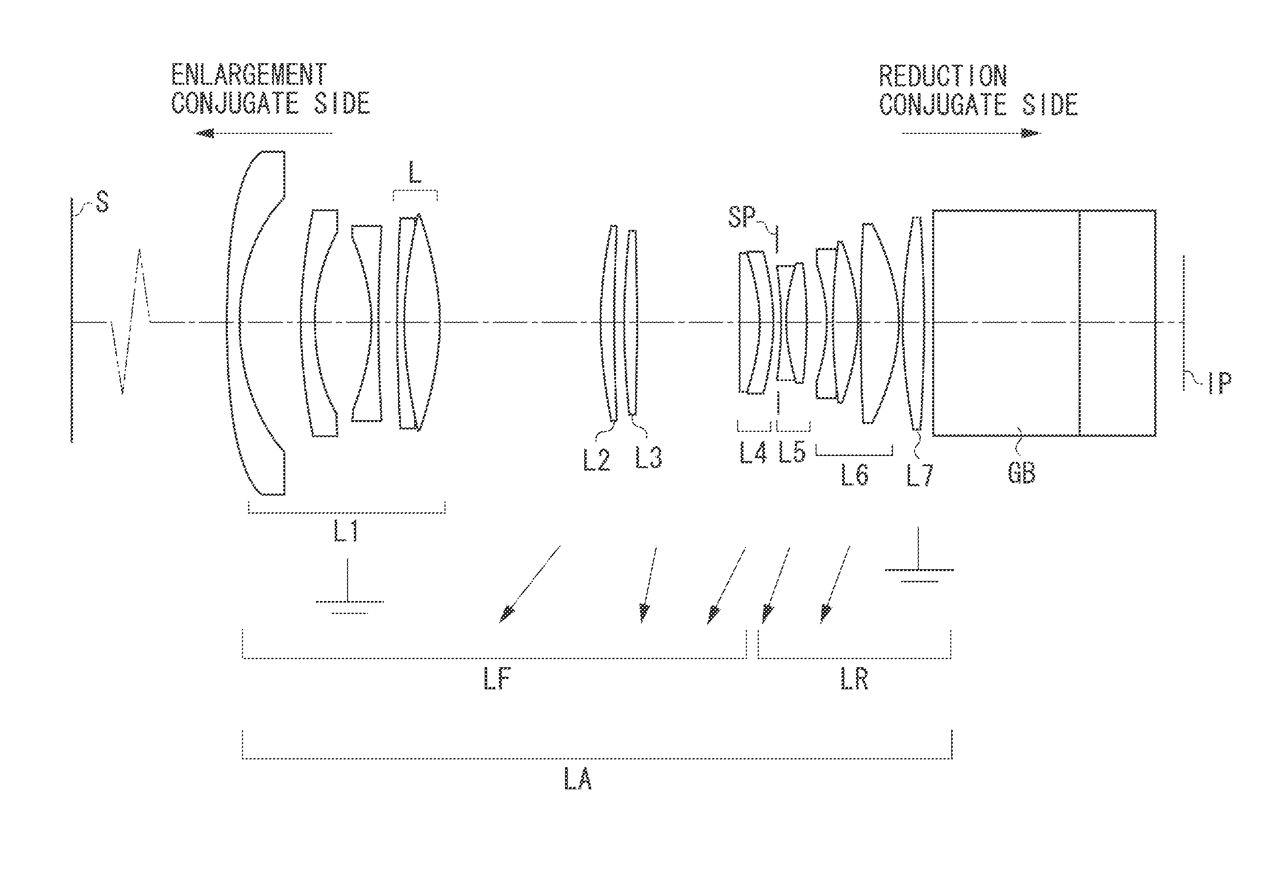
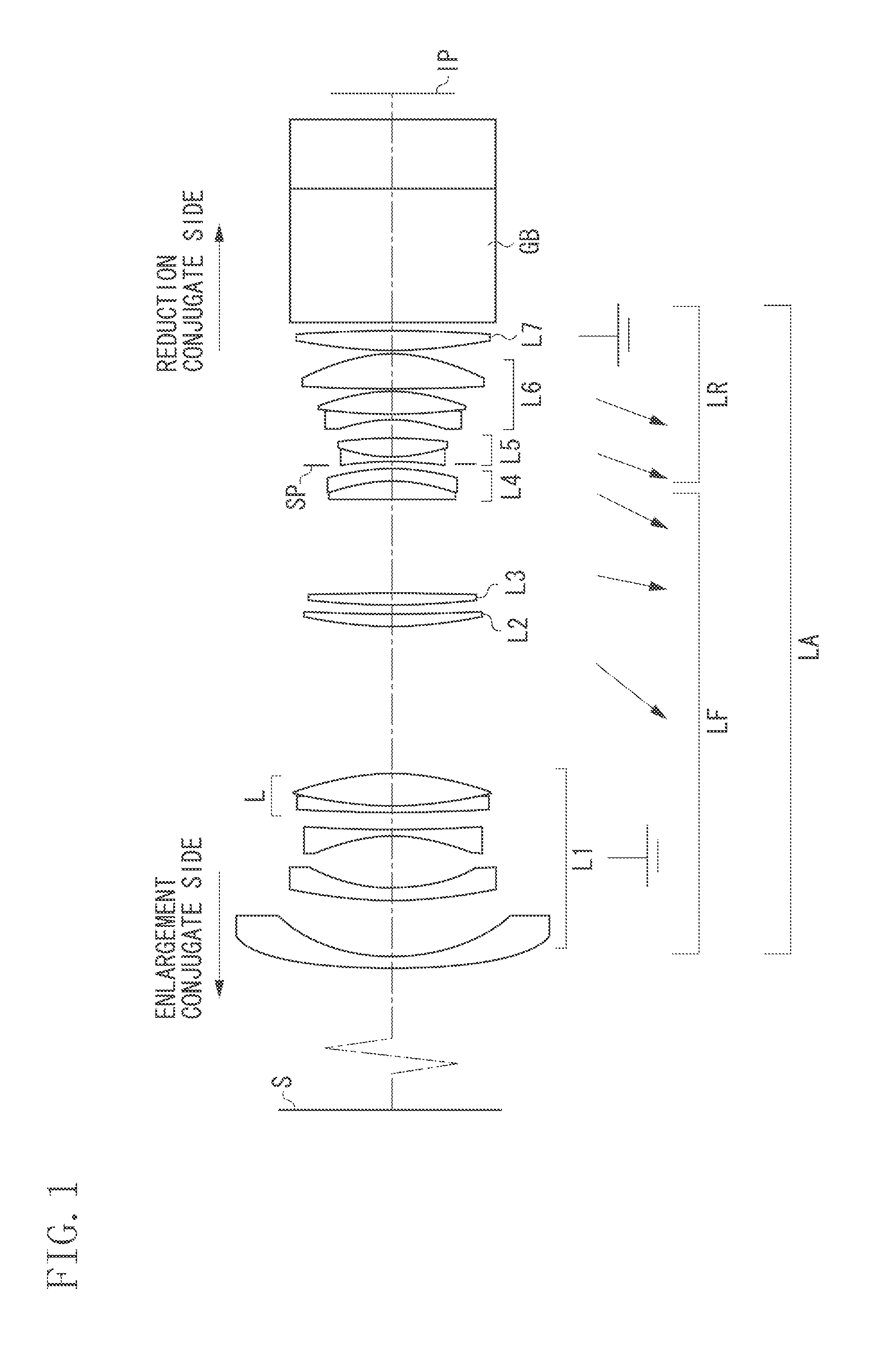
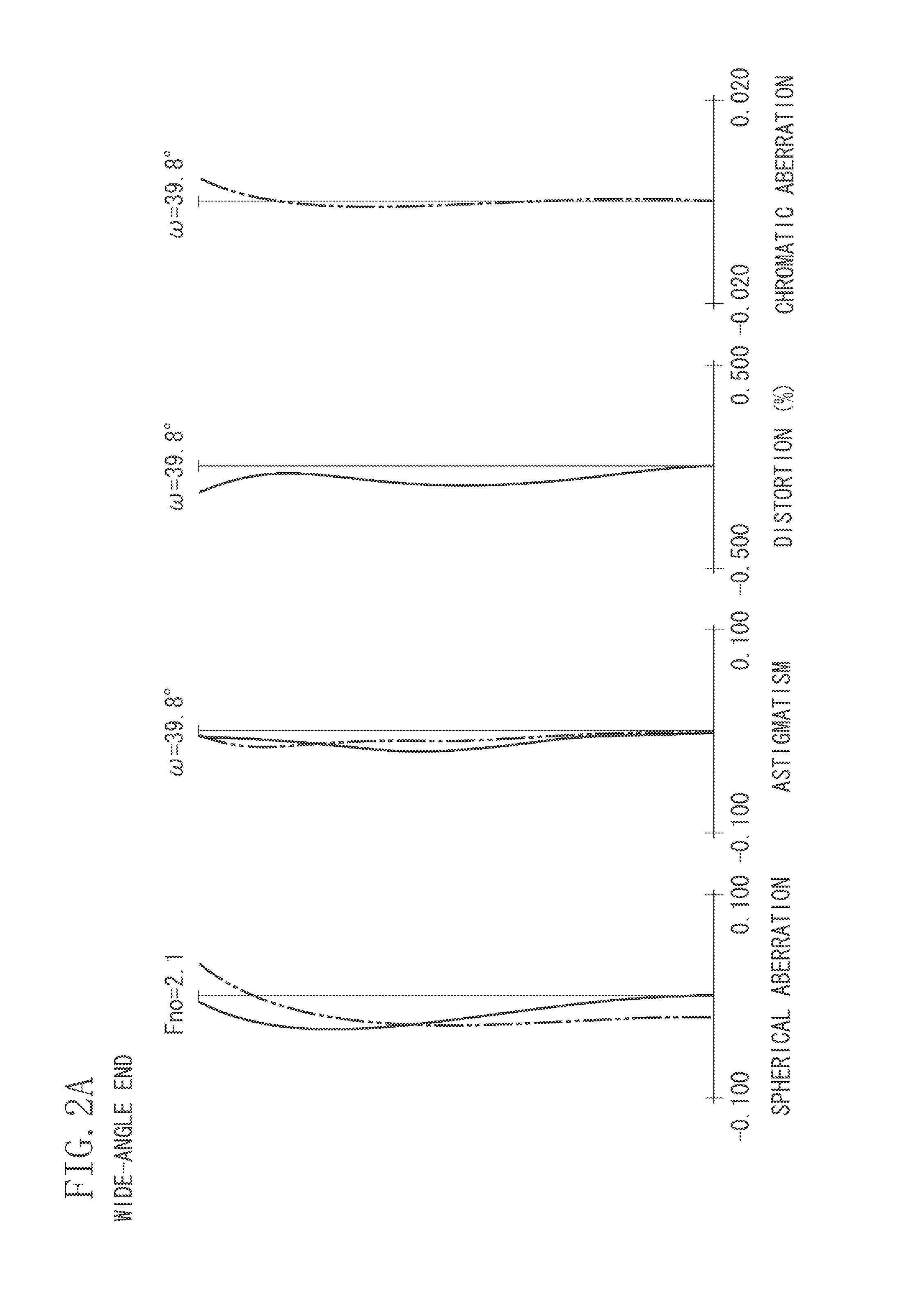
a technology of optical system and image projection apparatus, applied in the field of optical system, can solve the problems of significant distortion and lateral chromatic aberration, affecting the correction of various kinds of aberration, and affecting the effect of light having a short wavelength, so as to achieve less lateral chromatic aberration and distortion, and facilitate long-back focus , favorable telecentricity
- Summary
- Abstract
- Description
- Claims
- Application Information
AI Technical Summary
Benefits of technology
Problems solved by technology
Method used
Image
Examples
numerical example 1
[0077]
Surface dataSurfaceEffectiveno.rdndνddiameterθ 1*219.4883.001.5163364.162.34 231.35716.3449.34 3*68.1163.281.7725049.640.51 429.19514.7734.90 5−30.9801.801.5952267.733.15 6146.8724.8834.89 7190.9332.001.9228618.937.260.6495 875.4888.971.7204734.737.890.5834 9−44.004(Variable)38.601066.4573.831.4874970.234.7611520.687(Variable)34.4312110.7833.271.8080922.832.9313−559.048(Variable)32.5414335.9575.161.5163364.124.6315−26.3123.501.8830040.824.3616−39.169(Variable)24.7917 (Stop)∞0.7519.9118−66.3751.301.8502632.319.921926.8315.441.5163364.120.0120−47.104(Variable)20.9321−23.8711.501.8502632.322.432293.3676.451.5163364.126.1923−29.9860.5028.2124156.79710.051.4387594.933.1525−30.236(Variable)35.252677.3145.301.8080922.837.8827−302.7402.7537.6228∞37.841.5163364.140.0029∞19.501.8051825.440.0030∞40.00Image∞planeAspheric surface dataFirst surfaceK = 0A4 = 7.17103e−006A6 = −5.60430e−009A8 = 6.08849e−012A10 = −3.74125e−015A12 = 1.32338e−018Third surfaceK = 0A4 = −4.10143e−006A6 = 1.70376e−0...
numerical example 2
[0078]
SurfaceEffectiveno.rdndνddiameterθ 1*545.4893.001.5163364.162.99 260.02912.3556.94 3*156.6523.001.7725049.644.72 427.55619.1936.43 5−36.9141.801.5952267.733.60 6201.0696.6234.77 7−266.3532.001.9228618.936.720.6495 8347.1200.3037.57 9210.2607.551.7204734.737.990.583410−42.892(Variable)38.6011106.2073.491.4874970.236.1012−4185.435(Variable)35.931374.5613.971.7618226.535.13144474.99016.0134.5615∞(Variable)28.20(Flare-cutstop)16237.1975.341.5163364.125.4817−26.7863.061.8830040.825.2118−40.110(Variable)25.5919 (Stop)∞0.6920.4420−75.9831.301.8502632.320.452123.2516.371.5163364.120.7622−37.163(Variable)21.5423−22.9791.501.8502632.322.0724216.6140.3025.1625140.1865.861.5163364.126.0626−31.1931.8427.7527−283.5157.001.4387594.931.5928−27.977(Variable)32.892977.3145.301.8080922.835.4230−302.7402.7535.2631∞37.841.5163364.140.0032∞19.501.8051825.440.0033∞40.00Image∞planeAspheric surface dataFirst surfaceK = 0A4 = 7.71589e−006A6 = −6.26043e−009A8 = 8.48317e−012A10 = −8.17005e−015A12 = 4.994...
numerical example 3
[0079]
SurfaceEffectiveno.rdndνddiameterθ 1*847.4583.001.6510056.259.68 228.10213.6045.18 3*63.7473.001.7725049.639.91 436.37510.6635.60 5−86.2151.801.5952267.734.28 6119.4299.2334.20 7−44.7752.001.9228618.934.760.6495 81714.4428.421.6541239.737.420.5737 9−33.07426.4038.6010197.1285.331.7282528.540.0111−72.25733.6439.921229.6033.081.8080922.819.9013185.0700.6518.9314−407.9081.601.7725049.618.601531.8648.8517.0616−75.2233.591.4874970.216.2417−17.4171.601.8830040.816.3218−24.7031.3016.8619 (Stop)∞5.7216.392087.9821.601.8502632.318.182117.5037.941.5163364.118.4022−17.8411.2619.3323−16.4681.601.8502632.319.252449.8126.271.5163364.122.8125−33.1784.3825.0326598.8939.691.4387594.931.5727−23.4420.5033.1228397.6523.301.8080922.833.9929−109.4862.7534.0730∞37.841.5163364.140.0031∞19.501.8051825.440.0032∞40.00Image∞planeAspheric surface dataFirst surfaceK = 0A4 = 1.36304e−005A6 = −1.77502e−008A8 = 2.19429e−011A10 = −1.54325e−014A12 = 5.27346e−018Third surfaceK = 0A4 = −1.34503e−005A6 = 8.29440e−...
PUM
 Abstract
Description
Claims
Application Information
 - R&D
- Intellectual Property
- Life Sciences
- Materials
- Tech Scout
- Unparalleled Data Quality
- Higher Quality Content
- 60% Fewer Hallucinations
Browse by: Latest US Patents, China's latest patents, Technical Efficacy Thesaurus, Application Domain, Technology Topic, Popular Technical Reports.
© 2025 PatSnap. All rights reserved.Legal|Privacy policy|Modern Slavery Act Transparency Statement|Sitemap|About US| Contact US: help@patsnap.com


