Bolt-hole cap for bolt hole in linear rail

Active Publication Date: 2014-07-17
CHIEFTECH PRECISION
View PDF5 Cites 2 Cited by
  • Summary
  • Abstract
  • Description
  • Claims
  • Application Information

AI Technical Summary

Benefits of technology

[0014]Still further another, the contact portion is connected to the metal cover by way of injection molding. Besides, the way of connection between the contact portion and the metal cover comprises a first connecting part connected to the metal cover, and a second connecting part is formed on the contact portion by way of injection molding so as to be connected to the first connecting part. For example, the first connecting part of the metal cover is a metal groove and the second connecting part of the contact portion is an insertion so that when the contact portion is connected to the metal cover, the insertion is inserted into the metal groove so as to securely connect the metal cover and the contact portion.
[0015]One aspect of the present invention is that the radial protrusions support the bolt-hole cap to increase the strength of the bolt-hole cap, and the protrusions are laterally and plastically deformed (preferably, not elastic deformation) to contact the bolt. Even if the bolt has uneven tolerances, the bolt-hole cap is in flush with the rail.
[0016]Another aspect of the present invention is that the annular recess

Problems solved by technology

However, during the hammering action, the top surface of the bolt-hole cap may not be in flush with the surface of the rail due to uneven hammering force.
However, the distal end of the cone-shaped part cannot provide sufficient force even the cone-shaped part is deformed.
However, the less the tolerance is maintained, the higher manufacturing cost is occurred.
It is noted that the friction is not sufficient fo

Method used


Image

  • Bolt-hole cap for bolt hole in linear rail
  • Bolt-hole cap for bolt hole in linear rail
  • Bolt-hole cap for bolt hole in linear rail

Examples


Embodiment Construction

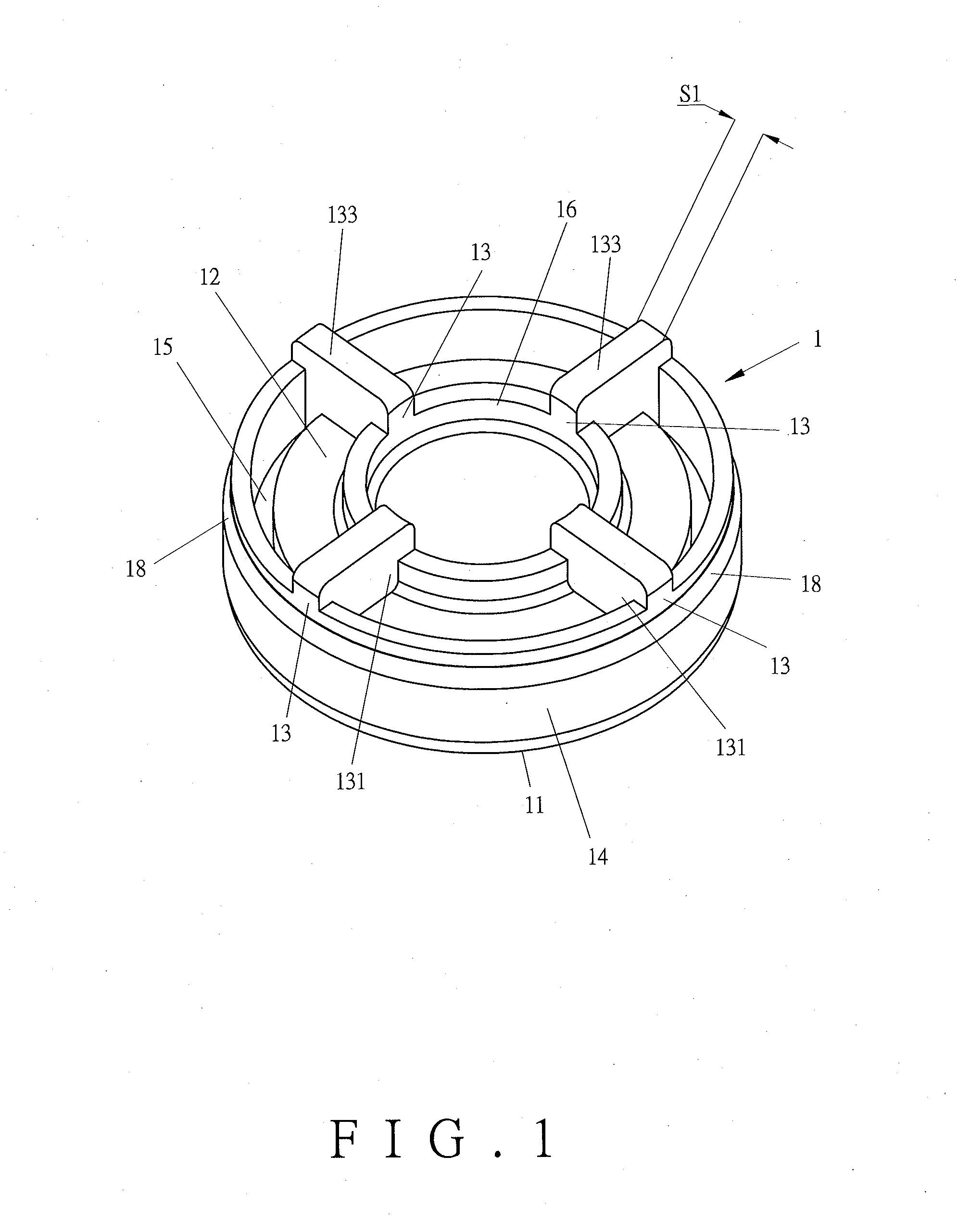
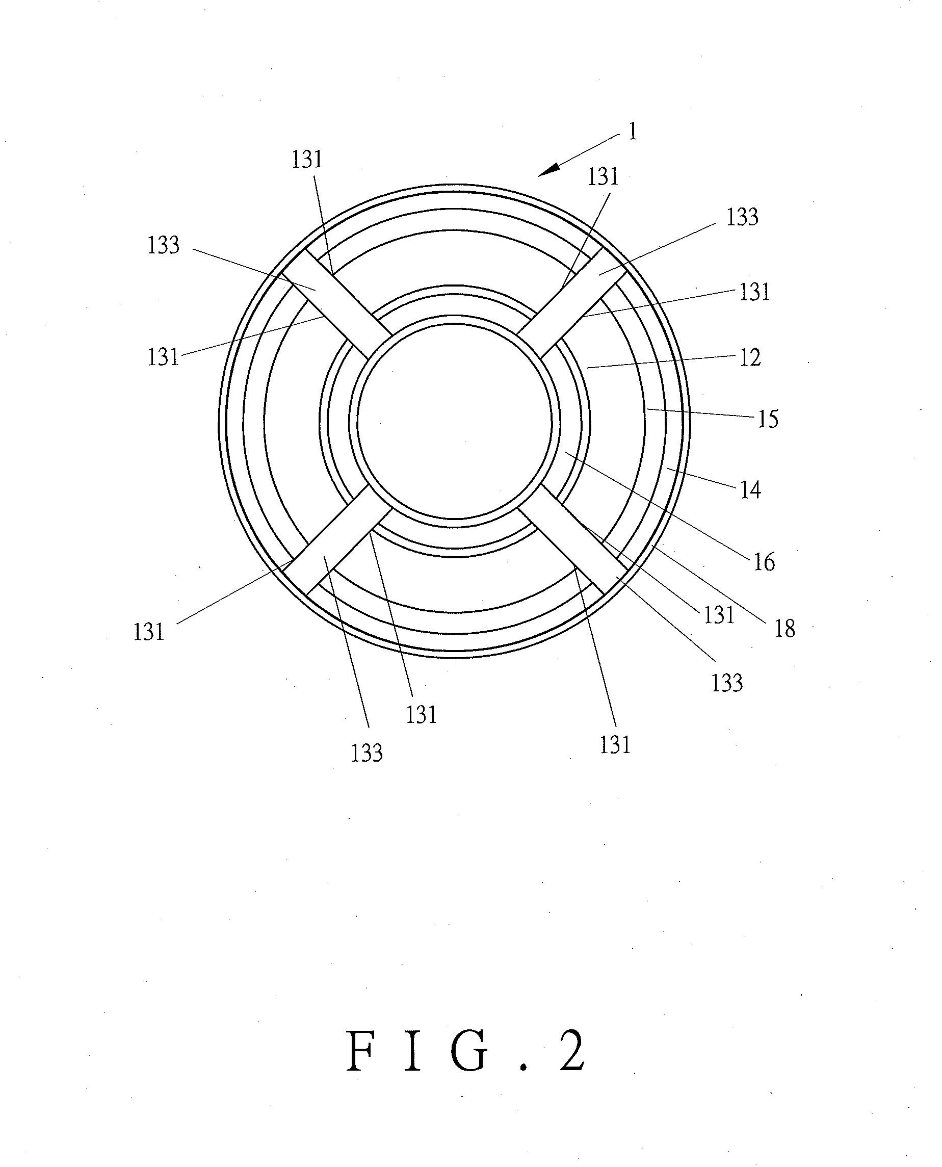
[0037]Referring to FIGS. 1 to 3, the bolt-hole cap 1 of the present invention comprises a top face 11 which is a flat face, and a bottom face 12, and multiple protrusions 13 extend from the bottom face 12. These protrusions 13 are made by plastic material and have a thickness. The protrusions 13 evenly arranged on the bottom face 12 in a circle manner. Each protrusion 13 extends radially from the inner portion toward the outer portion of the bolt-hole cap 1. Each protrusion 13 has two side faces 131 and an end face 133 which is connected between the two side faces 131. The end face 133 has a first width S1. The bolt-hole cap 1 has an annular outer wall 14 extending from the periphery thereof. A guide face 18 is tapered and annularly arranged on the bottom of the outer wall 14. The outer wall 14 extends in the direction the same as that of the protrusions 13. An annular recess 15 is defined in the bottom face 12 of the bolt-hole cap 1 and located adjacent to the outer wall 14. The bo...


PUM


Abstract

A bolt-hole cap for sealing the bolt hole of a rail includes a top face and a bottom face from which multiple protrusions extend. Each protrusion extends radially from inner portion toward outer portion of the bolt-hole cap. Each protrusion has two side faces and an end face connected between the two side faces. The end face has a first width. When the bolt-hole cap is inserted into a bolt hole and the top face of the bolt-hole cap is in flush with the top face of the rail, the end face of each of the protrusions contacts the bolt in the bolt hole. The protrusions are plastically deformed toward the side faces and the end face has a second width which is wider than the first width, so that the bolt-hole cap has sufficient strength to keep the top thereof flushing the top of the rail.

Description

FIELD OF THE INVENTION[0001]The present invention relates to a bolt-hole cap for a bolt hole in which a bolt is locate, and more particularly, to a bolt-hole cap for a bolt hole in a linear rail so as to prevent foreign objects from entering the bolt hole.BACKGROUND OF THE INVENTION[0002]The conventional bolt-hole cap for a bolt hole in a rail is disclosed in FIGS. 13 and 14, and generally comprises a slider D movably mounted to a rail E, and the slider D is endlessly moved along the rail E. Multiple bolt holes F are located at the rail E and each has a bolt G extending therethrough so as to fix the rail E to a fixed body H. When the slider D moves along the rail E, the slider D has an end seal connected thereto which is matched on the rail E to prevent foreign objects from entering the slider D to damage the slider D. However, the dust or foreign objects are easily hidden in the bolt holes F of the rail E. When the slider D passes over the bolt holes F, the dust or foreign objects ...

Claims


Application Information

Patent Timeline
IPC IPC(8): F16B37/14
CPCF16B37/14F16C29/004F16C29/0645F16C29/082
Inventor HSU, MING-CHE
Owner CHIEFTECH PRECISION
Why Eureka
Try Eureka