
Dental implantation system and method using magnetic sensors

a technology of magnetic sensors and implanted teeth, which is applied in the field of dental implanted teeth system and magnetic sensor, can solve the problems of inconvenient use, inconvenient use, and limited images provided by conventional systems that rely on optical (viewable) images, and achieves inconvenient use. use, and the accuracy of computer-aided imaging systems is not particularly high,

Inactive Publication Date: 2014-07-17
PRECISION THROUGH IMAGING
View PDF22 Cites 41 Cited by
  • Summary
  • Abstract
  • Description
  • Claims
  • Application Information

AI Technical Summary

Benefits of technology

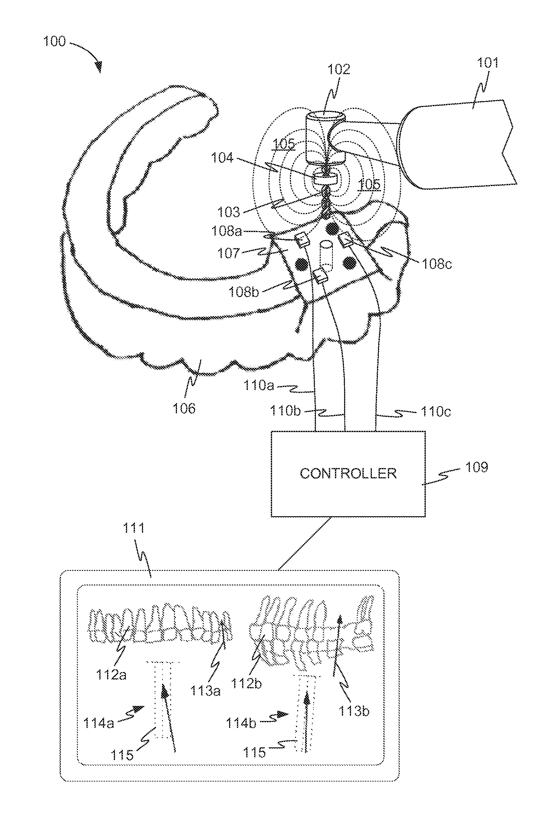
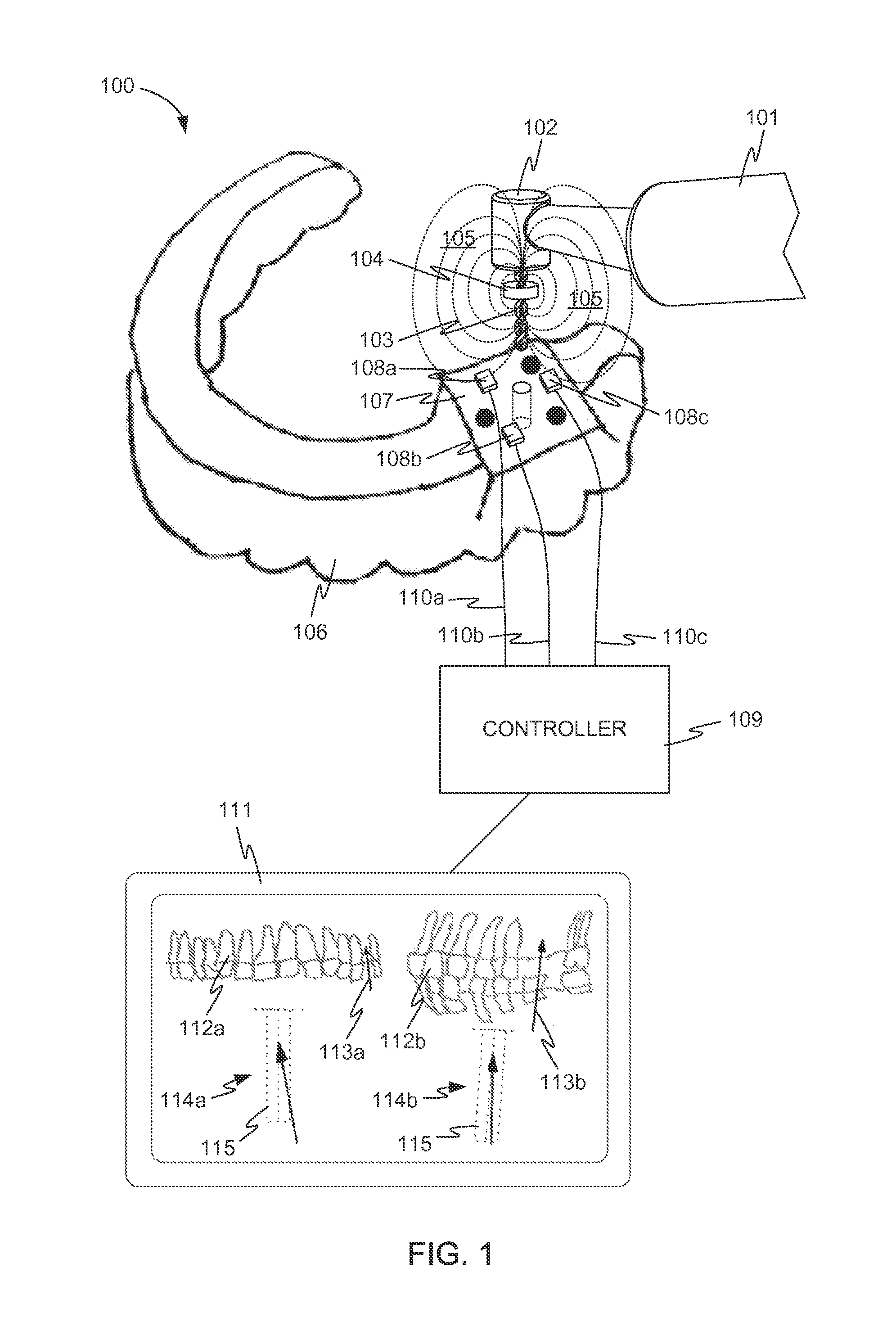
The patent describes a system for indicating the location of a dental drill using sensors that detect a magnetic field. The sensors are placed in the dental handpiece and produce signals that can be used to determine the drill's location in relation to the patient's dentition. This information can be displayed on a computer screen and used to guide the dental drill during dental procedures. The system is calibrated to ensure accurate location tracking and can be used in dental education and training. The patent also describes a sensing device that includes a carrier with circuit traces and a set of electronic sensors mounted around a through hole, making it suitable for use in dental patients. The sensors are sensitive to changes in the magnetic field caused by the dental drill and produce signals that can be used to determine the drill's location. The system uses the sensor outputs to create a visual representation of the dental drill's location in relation to the patient's dentition.

Problems solved by technology

Conventional systems that provide such imaging can be cumbersome, complicated, and difficult to use.
Moreover, the images provided by systems that rely on optical (viewable) images can be limited by images that are obscured by fluids, including blood and water found at the implant site during drilling.
In addition, some computer-assisted imaging systems are not especially accurate in determining location of anatomical structures and instruments, nor are they especially accurate in updating such location information in real-time during the drilling procedure.

Method used


Image

  • Dental implantation system and method using magnetic sensors
  • Dental implantation system and method using magnetic sensors
  • Dental implantation system and method using magnetic sensors

Examples


embodiments

Embodiment 1

[0145]A system for indicating the location of a dental drill, the system comprising: a dental handpiece comprising the dental drill; and a plurality of sensors that detect a magnetic field and produce a set of respective sensor outputs, the sensor outputs usable at least in part to indicate the location of the dental drill.

embodiment 2

[0146]The system of embodiment 1, further comprising a magnetic element that is fixed in relation to the dental drill and generates the magnetic field.

embodiment 3

[0147]The system of embodiment 1, wherein the dental drill is magnetized and generates the magnetic field.


PUM


Abstract

Provided herein, inter alia, is a system for indicating the location of a dental drill includes a dental handpiece, which further includes the dental drill. A plurality of sensors detect a magnetic field and produce a set of outputs, which are usable at least in part to indicate the location of the dental drill. The sensor outputs may be processed to produce an indication of the spatial relationship of the drill to a patient's dentition. The indication is preferably graphical, and may be presented to a dental professional using the system during an implant procedure to provide visual feedback about the procedure. The indication may be repeatedly updated, substantially in real time.

Description

[0001]This application is a continuation of PCT International Patent Application No. PCT / US2012 / 046789, filed Jul. 13, 2012, which in turn claims priority from U.S. Provisional Patent Application No. 61 / 507,956 filed Jul. 14, 2011 and titled “Dental Implantation System and Method Using Magnetic Sensors”, the entire disclosures of each of which are hereby incorporated by reference herein for all purposes.BACKGROUND[0002]Dental implant surgery involves placing a prosthetic device such as one or more artificial replacement teeth in the mouth of a patient. Such prosthetic devices must be precisely placed in the mouth for the best aesthetic and functional results. Precise placement of the prosthetic device requires suitable preparation of the implant site with respect to surrounding tissue and bone. The prosthetic device typically comprises a tooth implant abutment, a pontic attached thereto, and a tooth implant fixture that extends from the abutment and is received into an implant shaft...

Claims


Application Information

Patent Timeline
IPC IPC(8): A61C1/08A61B5/00A61B5/05
CPCA61C1/082A61B5/682A61B5/05A61C1/084A61B2034/2072A61B2034/2051B65D21/0209B65D25/40B65D51/245B65D83/00B65D2583/005
Inventor MOFFSON, ALLEN M.PRSHA, JEFFREY A.WHEATLEY, III, CHARLES E.
Owner PRECISION THROUGH IMAGING
Learn More