Al technical title is built by PatSnap Al team. It summarizes the technical point description of the patent document.
a technology of fixing clip and fixing rod, which is applied in the direction of snap fasteners, buckles, mechanical devices, etc., can solve the problems of inability to move from the holding position against the swivel direction, and inability to pull out the line from the receiving space, so as to improve the fixation effect of the lin
Active Publication Date: 2014-07-24
ITW FASTENER PRODS
View PDF4 Cites 11 Cited by
Summary
Abstract
Description
Claims
Application Information
AI Technical Summary
This helps you quickly interpret patents by identifying the three key elements:
Problems solved by technology
Method used
Benefits of technology
[0004]It is the object of the invention to provide a fixation clip which provides for an easy assembly of the line, but provides an improved fixation of the line.
[0005]For the solution of this object there is provided a fixation clip for at least one line, with a frame which defines a receiving space for the line, into which space the line can be introduced such that the frame encloses the line in circumferential direction, wherein an insertion opening for the line is provided at the frame, and with at least one swivel arm mounted on the frame, which can be moved from a holding position, in which the line is fixed in the receiving space, in swivel direction into an assembly position in which the line can be introduced into the receiving space through the insertion opening, wherein there is provided a web which with a first end is mounted on the swivel arm and with a second end is mounted on the inside of the frame, wherein the web includes at least one joint and is folded in the assembly position. The web is attached to the swivel arm and to the frame such that a movement from the holding position against the swivel direction is not possible. During such movement the web is stretched or subjected to tension and thus reliably holds the swivel arm in the holding position. The joint provided in the web has the advantage that when pivoting the swivel arm into the assembly position the web can easily be folded together, so that when pivoting the swivel arm into the assembly position the web provides no resistance and in addition can be folded in a space-saving manner.
[0006]In particular in a generic fixation clip it furthermore is provided in accordance with the invention that at the swivel arm and / or at the frame a protrusion can be provided, which during pivoting of the swivel arm from the holding position against the swivel direction comes to abut against a contact surface at the frame and / or at the swivel arm and blocks pivoting of the swivel arm against the swivel direction. In combination with the contact surface this protrusion has the same effect as a web according to the invention, namely that pivoting of the swivel arm against the swivel direction out of the receiving space is prevented. The protrusion can be arranged for example outside the receiving space or on the outside of the frame. This offers the advantage that within the frame no additional components are present, whereby the receiving space can completely be utilized for the line.
[0008]It is also possible that two swivel arms are provided, which are provided at opposite edges of the insertion opening and which are pivoted in opposite directions into the assembly position. On the one hand, this provides for a better hold of the line. On the other hand, the insertion opening can be designed larger, as the same can be closed by both swivel arms, whereby larger lines can be inserted into the fixation clip and the fixation clip can be used more flexibly.
[0010]It is, however, also possible that the web is at least partly bent in the holding position, so that a small movement of the swivel arm out of the holding position is possible, wherein in each case however pivoting of the swivel arm out of the receiving space is prevented. In particular, the web can rest against the line with a bent portion, so that the line additionally is supported by the web. In addition, pretensioning of the web can be effected by the inserted line, so that the same is subjected to tension and pivoting of the swivel arm out of the receiving space is prevented.
Problems solved by technology
The web is attached to the swivel arm and to the frame such that a movement from the holding position against the swivel direction is not possible.
The swivel arm preferably is mounted at an edge of the insertion opening, so that in the holding position the same can close the insertion opening or at least reduce the width of the insertion opening to such an extent that pulling out the line from the receiving space is not possible.
Method used
Image
Click on the blue label to locate the original text in one second.
Reading with bidirectional positioning of images and text.
Examples
Embodiment Construction
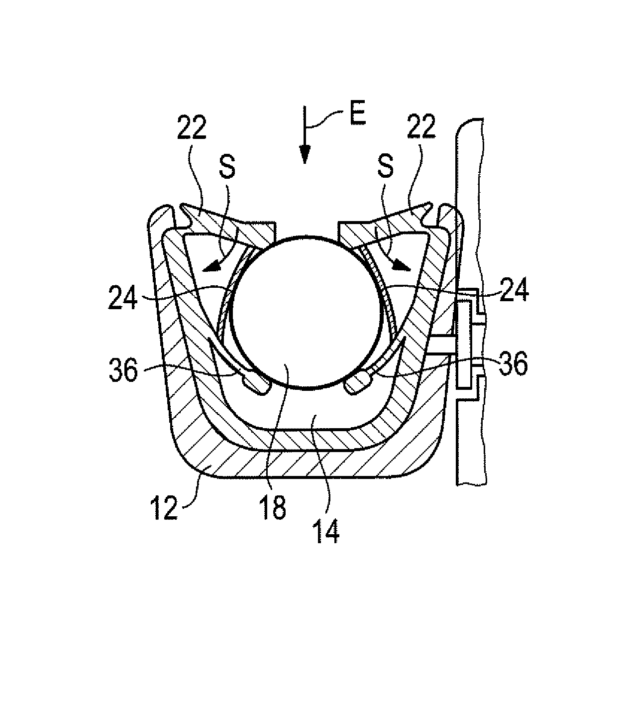
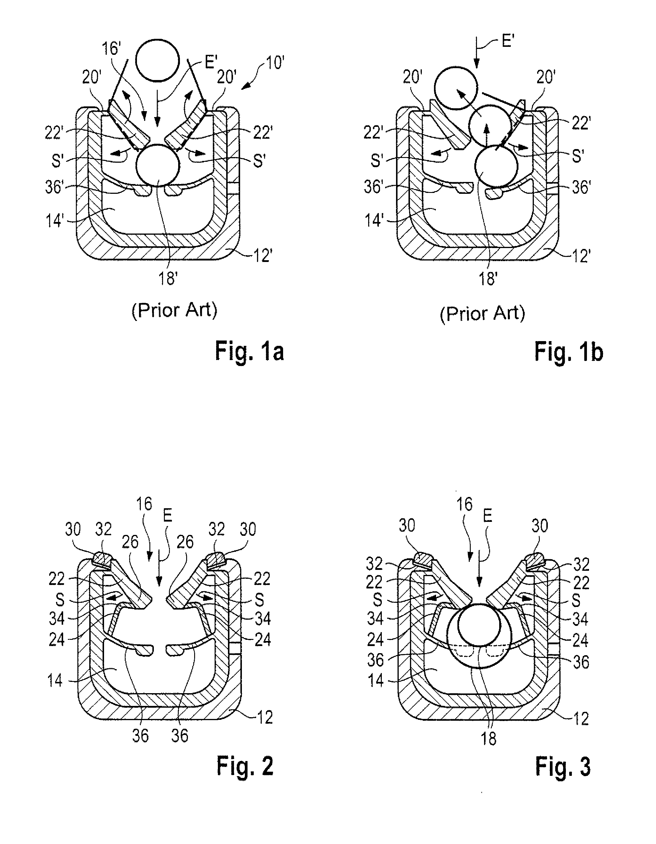
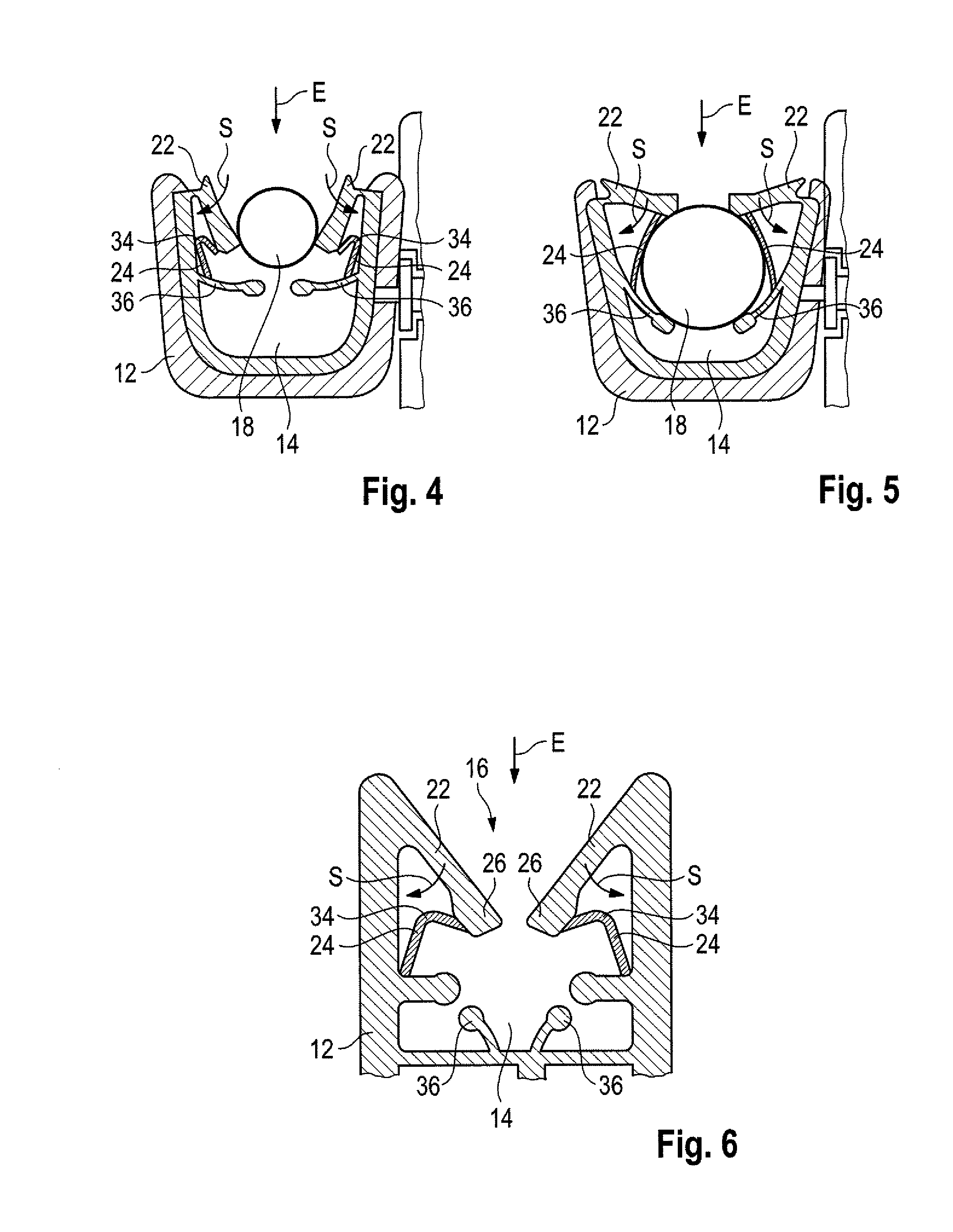
[0022]FIGS 1a and 1b show a fixation clip 10′ from the prior art. The fixation clip has a frame 12′ which in the embodiment shown here is formed substantially square and defines a receiving space 14′.
[0023]The frame 12′ has an interruption in circumferential direction U, which forms an insertion opening 16′ through which a line 18′ can be inserted into the receiving space 14′. At the edges 20′ of the receiving opening 16′ a swivel arm 22′ each is provided, which from the holding position shown here can be moved in a swivel direction S′ into the receiving space 14′ to assume an assembly position, in which the line 18′ can be inserted into the receiving space 14′ in an insertion direction E′. When the line 18′ is inserted completely, the swivel arms 22′ spring back into the holding position against the swivel direction S′, so that the line 18′ is fixed in the receiving space 14′.
[0024]In the receiving space 14′ supporting tabs 36′ furthermore are provided, which rest against the line ...
PUM
Abstract
In a fixation clip (10) for at least one line (18), with a frame (12) which defines a receiving space (14, 14a, 14b) for the line (18), into which space the line (18) can be introduced such that the frame (12) encloses the line (18) in circumferential direction, wherein an insertion opening (16, 16a, 16b) for the line (18) is provided at the frame (12), and with at least one swivel arm (22, 22a, 22b) mounted on the frame (12), which can be moved from a holding position, in which the line (18) is fixed in the receiving space (14, 14a, 14b), in a swivel direction (8) into an assembly position in which the line (18) can be introduced through the insertion opening (16, 16a, 16b) into the receiving space (14, 14a, 14b), a web (24) is provided, which with a first end is mounted on the swivel arm (22, 22a, 22b) and with a second end is mounted on the inside of the frame (12), wherein the web (24, 24a, 24b) includes at least one joint (34, 34a, 34b) and is folded in the assembly position.
Description
BACKGROUND OF THE INVENTION[0001]This invention relates to a fixation clip for at least one line, with a frame which defines a receiving space for the line, into which space the line can be introduced such that the frame encloses the line in circumferential direction, wherein an insertion opening for the line is provided at the frame, and with at least one swivel arm mounted on the frame, which can be moved from a holding position, in which the line is fixed in the receiving space, in swivel direction into an assembly position in which the line can be introduced into the receiving space through the insertion opening.[0002]Fixation clips of this type are used to be able to fix a line, for example a cable, in a simple way. Through the insertion opening, the line can easily be inserted into the frame of the fixation clip premounted for example on an attachment part and snap into place in said frame behind the swivel arms, so that a simple, tool-less fixation of the line is possible.[00...
Claims
Application Information
Patent Timeline
Application Date:The date an application was filed.
Publication Date:The date a patent or application was officially published.
First Publication Date:The earliest publication date of a patent with the same application number.
Issue Date:Publication date of the patent grant document.
PCT Entry Date:The Entry date of PCT National Phase.
Estimated Expiry Date:The statutory expiry date of a patent right according to the Patent Law, and it is the longest term of protection that the patent right can achieve without the termination of the patent right due to other reasons(Term extension factor has been taken into account ).
Invalid Date:Actual expiry date is based on effective date or publication date of legal transaction data of invalid patent.
Patent Type & Authority Applications(United States)