Scintillator
a technology of scintillator and ion beam, which is applied in the field of scintillator, can solve the problems of insufficient time for the fast component of fluorescence and insufficient light emission efficiency, and achieve the effect of improving the afterglow property of cesium iodide and high output level of light emission
- Summary
- Abstract
- Description
- Claims
- Application Information
AI Technical Summary
Benefits of technology
Problems solved by technology
Method used
Image

Examples
examples
[0046]Hereinafter, Examples of the invention will be described. However, the scope of the invention is not limited to the following Examples.
[0047]
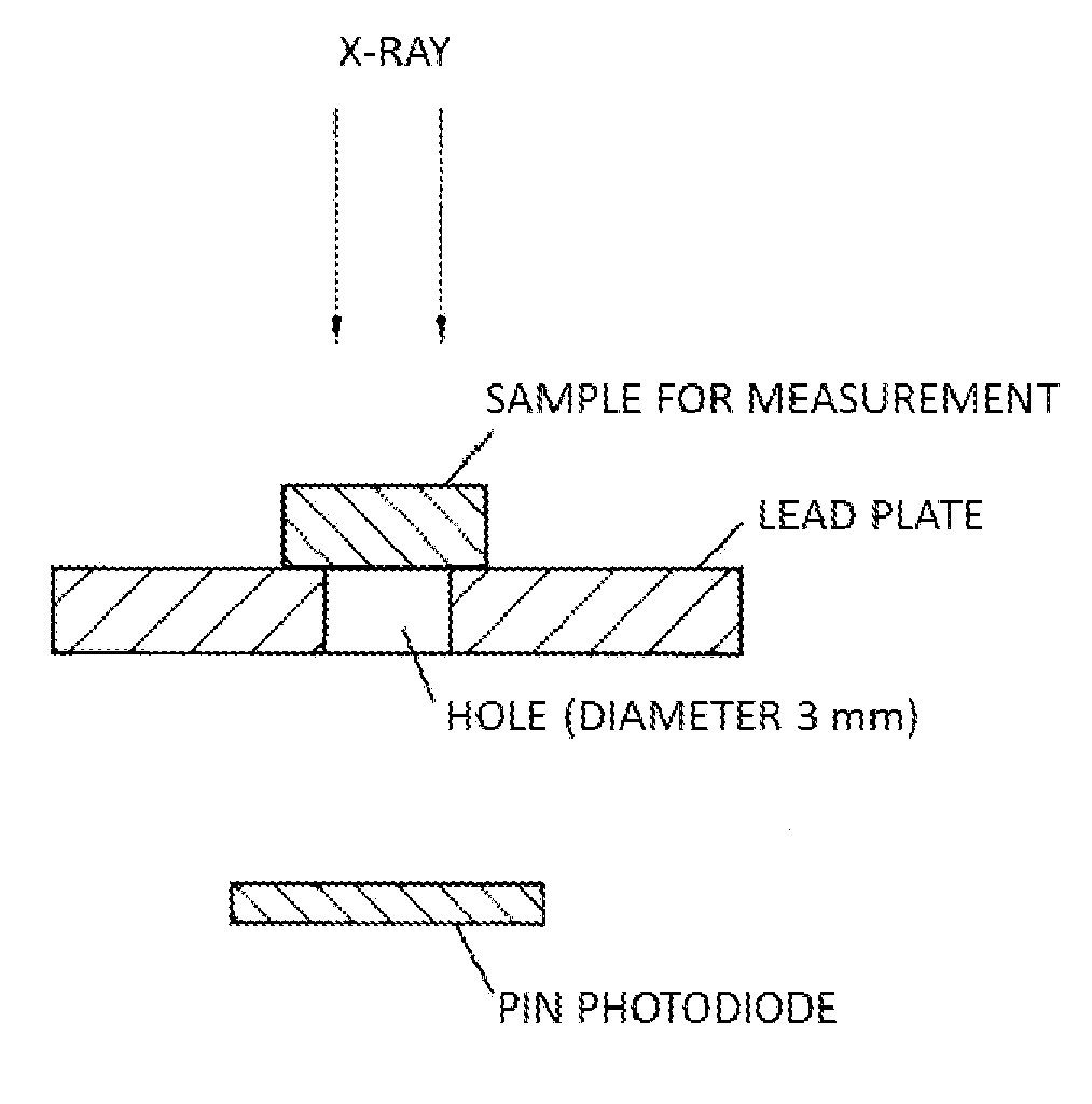
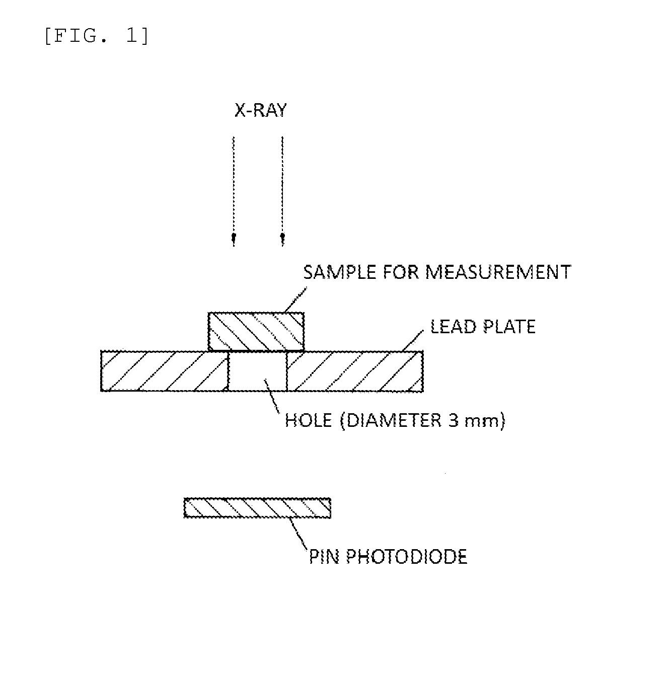
[0048]Output (nA) and afterglow (ppm) are measured using the measuring apparatus illustrated in FIG. 1.
[0049]A sample for measurement (scintillator disc) with a diameter of 8 mm and a thickness of 2 mm is used.
[0050]At this time, the output is an output of a photodiode when the scintillation light generated at a sample for measurement by irradiating the sample for measurement with predetermined X-ray is absorbed by a PIN photodiode, and the afterglow is an afterglow at a predetermined time after X-ray radiation.
[0051]A target formed of tungsten (W) was irradiated with an electron ray having an applied voltage of 120 kV and an applied current of 20 mA to generate X-ray, the sample for measurement was irradiated with this X-ray, and the output of the scintillation light and transmitted X-ray was measured by a PIN photodiode (S1723-5 manufac...
reference examples 1 and 2 , examples 1 to 6
Reference Examples 1 and 2, Examples 1 to 6, Comparative Examples 1 to 6
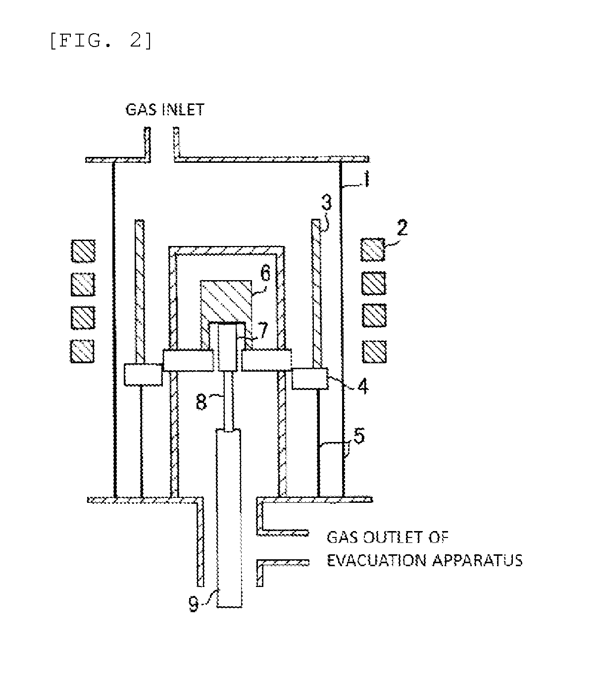
[0055]Each of the raw materials was weighed by a predetermined amount such that the amount of each of the elements is the value shown in Table 1, and mixed in a mortar, and then the mixture was set in a crystal growth apparatus illustrated in FIG. 2 and a crystal growth was performed. Here, doping amount of each of the added elements was expressed by atomic number percentage (at. %) with respect to Cs element in CsI, which is the host material.
[0056]Incidentally, CsI powder (99.999%) was used as the CsI raw material, TlI powder (99.999%) as the Tl raw material, BiI3 powder (99.999%) as the Bi raw material, AgI powder (99.999%) as the Ag raw material, SmI2 powder (99.9%) as the Sm raw material, YbI3 powder (99.9%) as the Yb raw material, TmI2 powder (99.9%) as the Tm raw material, Eu12 powder (99.9%) as the Eu raw material, and PbI2 powder (99.9%) as the Pb raw material.
[0057]The crystal growth was performed acco...
example 7
[0072]Crystal growth was performed according to the same procedure described in Examples 1 to 6 except that a cylindrical quartz ampoule with a cylindrical part diameter of 1 inch was used, and powders of the raw materials were weighed and mixed such that, among the raw materials, the doping amount of added elements was 0.50 at. % for Tl and 0.01 at. % for Bi, and sealed in the quartz ampoule. In addition, samples were taken from parts, which have different proportions of solidification, of the crystal thus obtained, and subjected to the evaluation of the output property and afterglow property as well as the analysis in the same manner as above.
PUM
| Property | Measurement | Unit |
|---|---|---|
| velocity | aaaaa | aaaaa |
| thickness | aaaaa | aaaaa |
| diameter | aaaaa | aaaaa |
Abstract
Description
Claims
Application Information
 - R&D Engineer
- R&D Manager
- IP Professional
- Industry Leading Data Capabilities
- Powerful AI technology
- Patent DNA Extraction
Browse by: Latest US Patents, China's latest patents, Technical Efficacy Thesaurus, Application Domain, Technology Topic.
© 2024 PatSnap. All rights reserved.Legal|Privacy policy|Modern Slavery Act Transparency Statement|Sitemap