Radiation temperature measuring device

Active Publication Date: 2020-03-12
ASAHI KASEI KK
View PDF0 Cites 0 Cited by
  • Summary
  • Abstract
  • Description
  • Claims
  • Application Information

AI Technical Summary

Benefits of technology

[0017]According to an aspect of the present invention, it is possible to detect at a sufficiently high level of output even in an infrared wavelength band opt

Problems solved by technology

A problem still remains in this method.
The problem is that since the reflectance of an actual target is not zero, an electromagnetic wave reflected by a surface of the target reaches the infrared sensor and the applied

Method used


Image

  • Radiation temperature measuring device
  • Radiation temperature measuring device
  • Radiation temperature measuring device

Examples


Embodiment Construction

[0028]Hereinafter, one embodiment of the present invention will be described with reference to FIG. 1 to FIG. 10.

(Structure of Radiation Temperature Measuring Device)

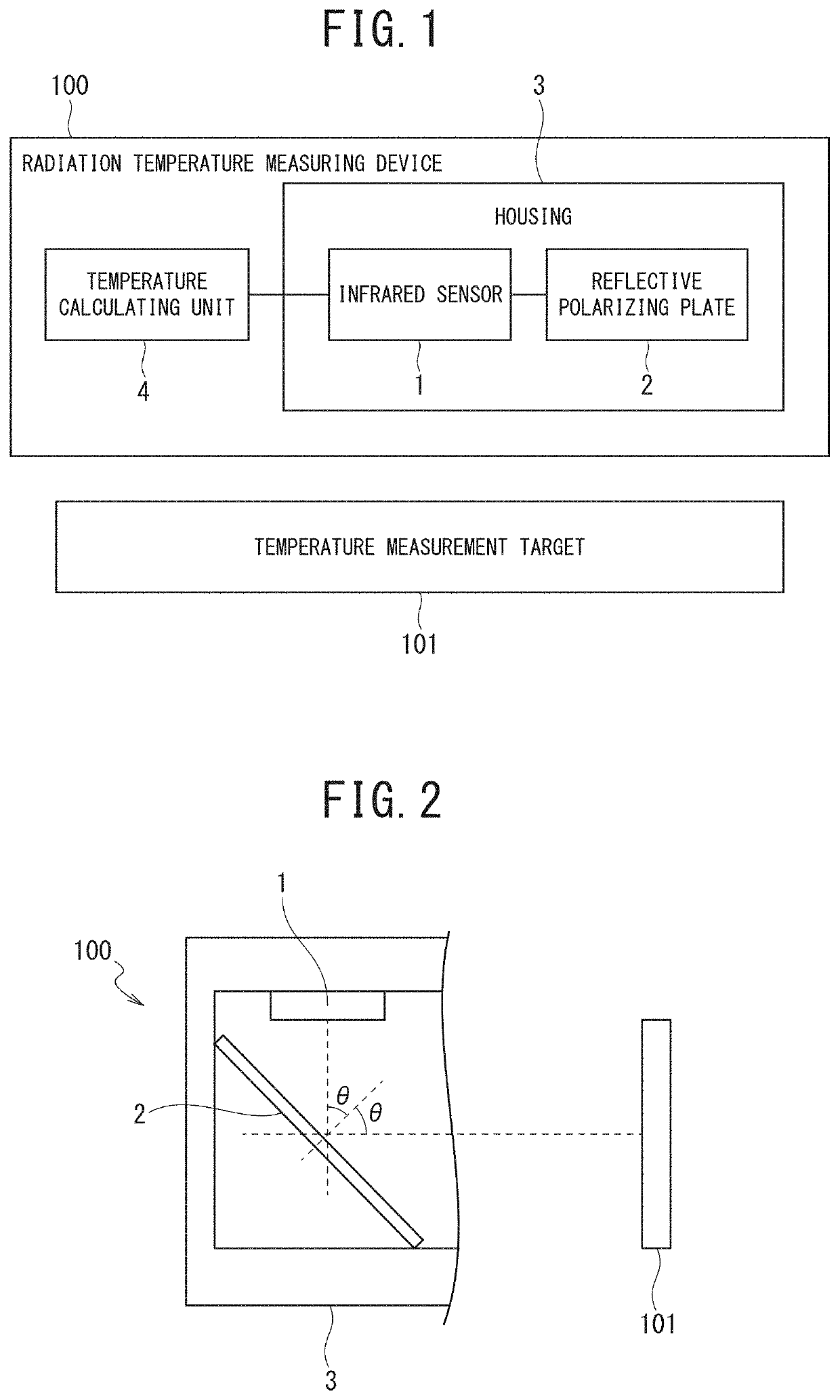
[0029]FIG. 1 is a block diagram illustrating a schematic structural example of a radiation temperature measuring device 100 according to the present embodiment. The radiation temperature measuring device 100 is a device configured to contactlessly measure a surface temperature of an object that is a measurement target by using an infrared sensor.

[0030]The infrared sensor is denoted by “1”. In the present invention, as will be described later, preferably, the wavelength band of the infrared sensor is not a conventional far infrared band (from 8 to 15 μm), but a middle infrared band (from 4 to 8 μm).

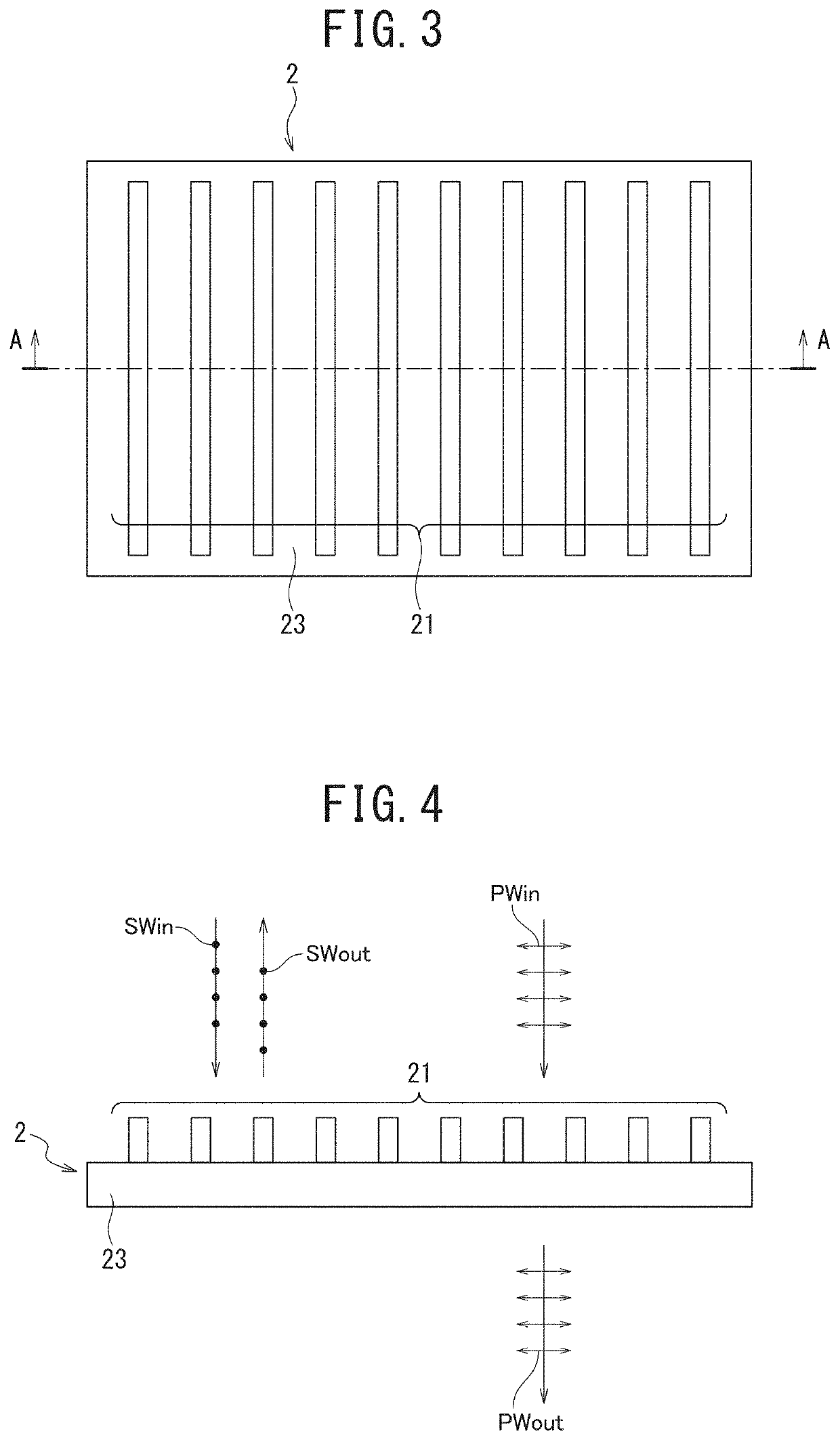
[0031]A reflective polarizing plate 2 is a reflection type polarizing plate. A reflective polarizing plate refers to a polarizing plate having a function of reflecting one component of an electromagnetic wave. An ordinary pola...


PUM


Abstract

An object of the present invention is to provide a radiation temperature measuring device capable of preventing reduction in the accuracy of temperature measurement due to an electromagnetic wave reflected by a measurement target. A radiation temperature measuring device includes a reflective polarizing plate configured to reflect a polarized wave of one direction in an electromagnetic wave radiated from an object to be measured and transmit or absorb a polarized wave of a direction perpendicular to the one direction and an infrared sensor configured to detect the polarized electromagnetic wave of the one direction reflected by the reflective polarizing plate.

Description

TECHNICAL FIELD[0001]The present invention relates to a radiation temperature measuring device using an infrared sensor.BACKGROUND ART[0002]Conventionally, there are known temperature measuring devices that contactlessly measure the temperature of a target by using an infrared sensor. Examples of applied products of the devices include radiation thermometers (contactless thermometers) and thermography (infrared cameras). Such temperature measuring devices utilize a principle that electromagnetic wave energy radiated from a target is determined only by the temperature of the target. In other words, using an infrared sensor enables measurement of the radiated energy in an infrared wavelength band that occupies a major part of the electromagnetic wave energy radiated from the target. The temperature of the target is calculated from a measured value of the radiated energy. The calculation of the temperature of the target uses, for example, Stefan-Boltzmann's Law of black body radiation ...

Claims


Application Information

Patent Timeline
IPC IPC(8): G01J5/08G01J5/06G01J5/10G02B5/30
CPCG01J5/10G02B5/3058G01J5/0825G01J5/06G02B5/30G01J5/59G01J5/0808G01J2005/604G01J5/48
Inventor SASAKI, HIROYUKISUGIYAMA, MASARU
Owner ASAHI KASEI KK
Why Eureka
Try Eureka