
Steerable twist-beam rear suspension

a rear suspension and twisting technology, applied in resilient suspensions, interconnection systems, vehicle components, etc., can solve the problems of limiting the driving dynamics of the torsion beam axle, the tendency toward lateral force overcompensation, and the more difficult isolation of vibration, so as to minimize the deviation of the steering angle of the wheel carrier, the effect of minimizing the track angle difference and minimizing the deviation of the steering angl

Inactive Publication Date: 2014-07-24
ZF FRIEDRICHSHAFEN AG
View PDF7 Cites 3 Cited by
  • Summary
  • Abstract
  • Description
  • Claims
  • Application Information

AI Technical Summary

Benefits of technology

The present invention is about a torsion beam axle for a vehicle that reduces differences in track angle. The axle has a cross-member that can be flat, rounded, or angular, and can be made from a single piece or multiple pieces. Each trailing arm supports a wheel carrier that pivots on a steering axis, and the carriers are connected to each other and to an actuating mechanism via a tie rod. This design allows for a smooth steering movement of the wheels.

Problems solved by technology

However, there are known to be limitations with regard to the driving dynamics of a torsion beam axle, particularly due to the design-related, unfavorable action of lateral forces which results in a tendency toward lateral force overcompensation and more difficult isolation of vibrations.
However, with the torsion beam axle known from that document—depending on the positioning and articulation of the tie rod—the arrangement of the tie rod and actuating mechanism may be kinematically inappropriate and, depending on the (sometimes) unilateral bouncing of the torsion beam axle, this can result in particular in track angle differences, i.e. erroneous steering angles of the steered rear wheels.

Method used


Image

  • Steerable twist-beam rear suspension
  • Steerable twist-beam rear suspension

Examples


Embodiment Construction

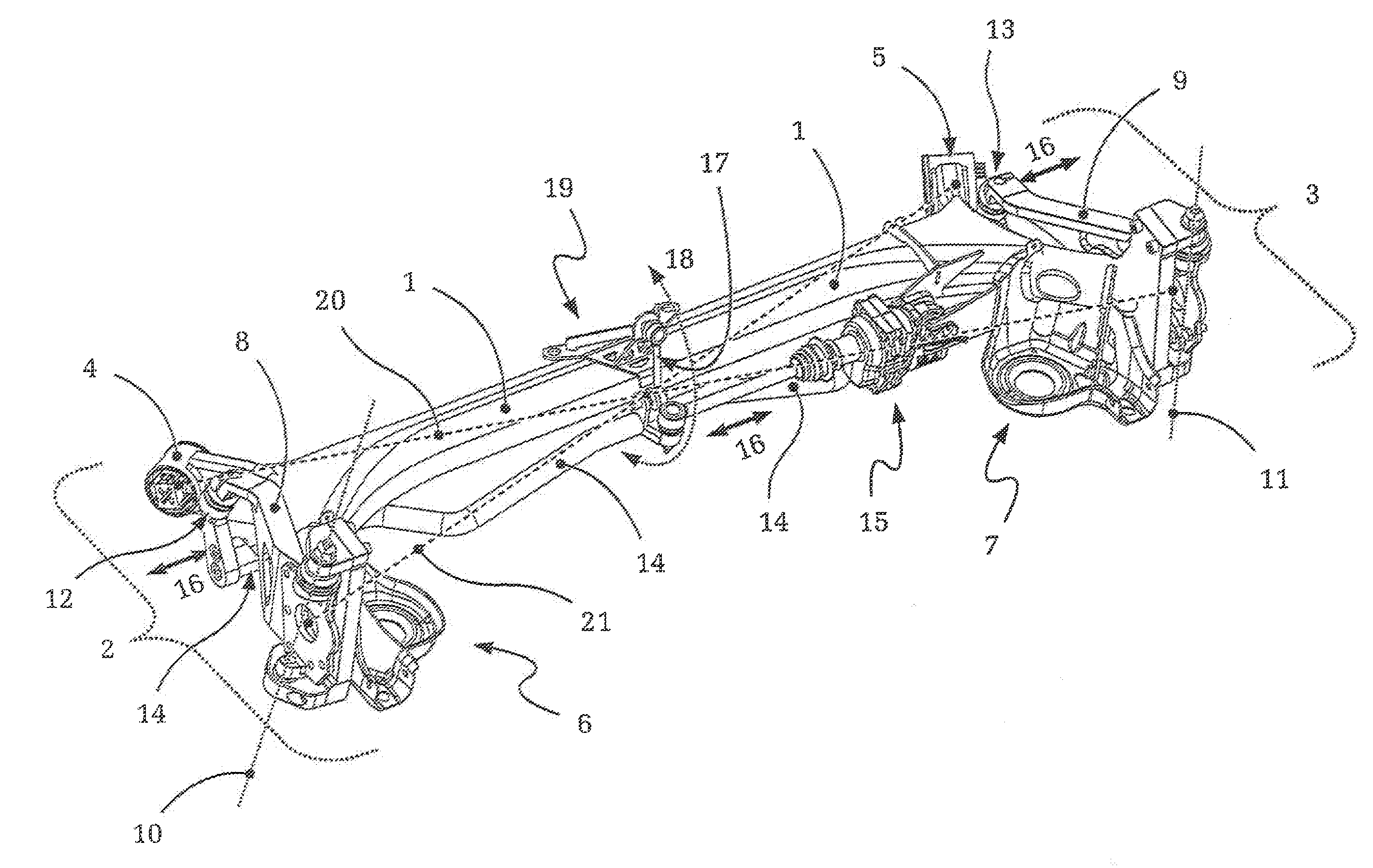
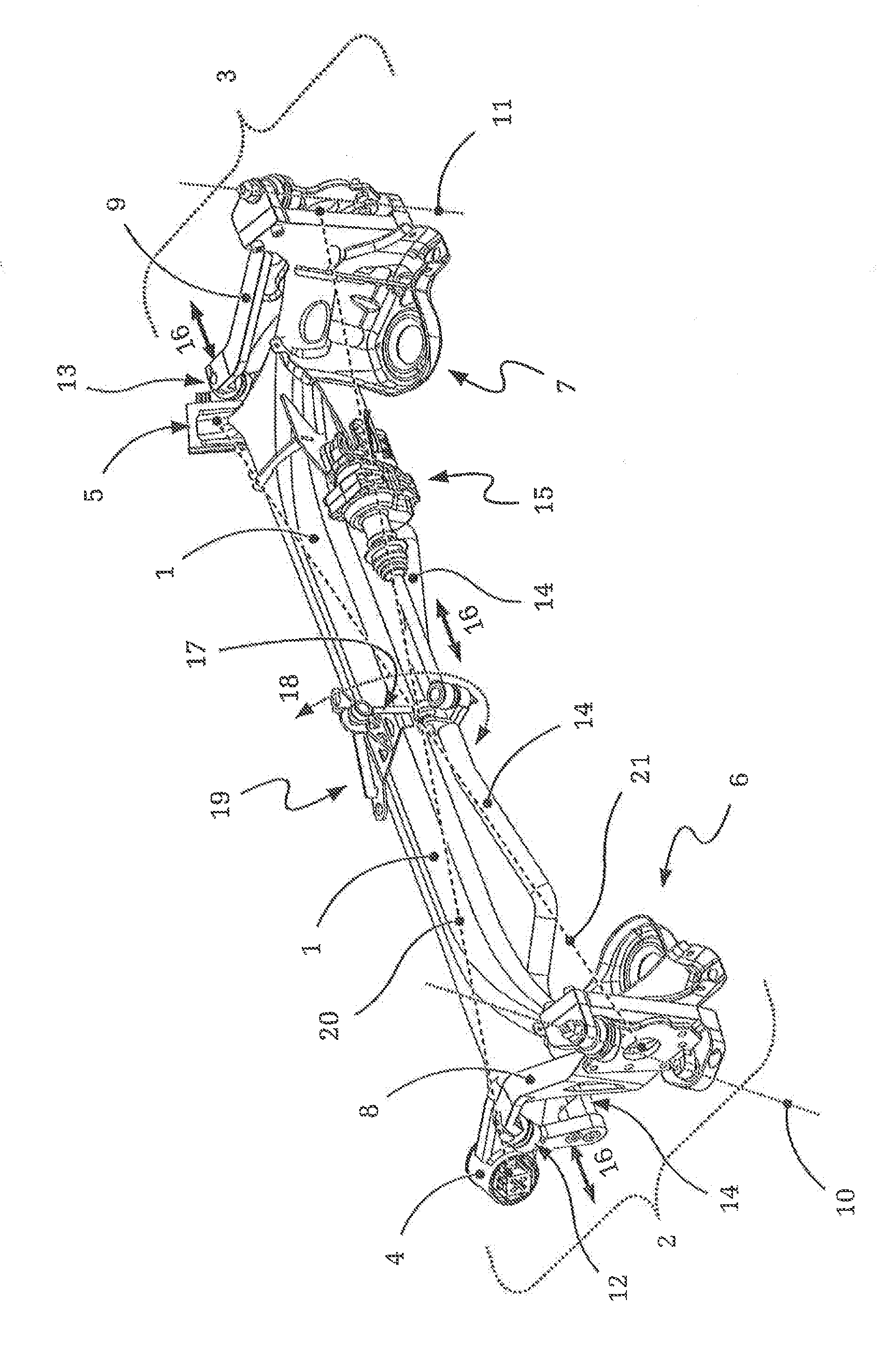
[0027]The FIGURE shows a steerable torsion beam axle, for example for the rear wheel suspension in a motor vehicle, according to an embodiment of the present invention. In the FIGURE can be seen the axle body, which comprises the torsionally compliant cross-member 1 and two trailing arms 2, 3 connected to the cross-member 1. On the trailing arms 2, 3 are arranged respective elastomeric mountings 4, 5 for connection to a vehicle chassis (not shown). The trailing arms 2, 3 comprise respective spring cups 6, 7 for holding the chassis springs (also not shown).

[0028]Furthermore, each trailing arm 2, 3 supports a wheel carrier 8, 9 which can in each case pivot about a respective, vehicle-related steering axis 10, 11 that extends vertically (or approximately so, apart from the steering axle inclination and the camber). The wheel carriers 8, 9 are connected by ball joints 12, 13 to a tie rod 14, which can be moved one way and the other along the direction indicated by the arrows 16 by means...


PUM


Abstract

A torsion beam axle for a wheel suspension of a motor vehicle. The torsion beam axle has a torsionally compliant transverse section. A trailing arm is fixed at each opposed end of the transverse section. Each trailing arm supports a wheel carrier that pivots about a respective steering axis. The wheel carriers are connected to one another via ball joints and a tie rod, and couple an actuating mechanism for producing steering movement of the wheel carriers about their respective steering axes. A kinematic coupling system is connected to the tie rod and designed to regulate the degree of freedom of rotational movement of the tie rod. A torsion beam axle in which—to minimizing track angle differences or unsymmetrical bouncing behavior—the tie rod and actuating mechanism maintain optimum kinematic conditions in all operating situations.

Description

[0001]This application is a National Stage completion of PCT / EP2012 / 067071 filed Sep. 3, 2012, which claims priority from German patent application serial no. 10 2011 082 768A filed Sep. 15, 2011.FIELD OF THE INVENTION[0002]The invention concerns a steerable twist-beam rear suspension for a wheel suspension of a motor vehicle.BACKGROUND OF THE INVENTION[0003]Torsion beam axles of the type concerned have characteristics common to both trailing arm axles and conventional solid axles. They are usually of simple design and consist essentially of two trailing arms which are resistant to torsion and bending, and which are connected to one another by a cross-member that is also resistant to bending but is compliant to torsion. Due to the torsionally compliant design of the cross-member, the wheel-carrying trailing arms can twist relative to one another. At the same time, the cross-member of the torsion beam axle acts as a roll stabilizer for the vehicle. In general the torsion beam axle en...

Claims


Application Information

Patent Timeline
IPC IPC(8): B60G11/18
CPCB60G11/18B60G21/051B60G2200/21B60G2200/44B60G2206/20B60G21/053B60G2204/1226
Inventor ELBERS, CHRISTOPHARAMAH, SIMONVORTMEYER, JENSWIESENTHAL, MARC
Owner ZF FRIEDRICHSHAFEN AG
Learn More