Method and apparatus for detecting combustion knock from the ionic current in an internal combustion engine

a technology of ionic current and internal combustion engine, which is applied in the direction of mechanical equipment, machines/engines, instruments, etc., can solve the problems of uncontrollable explosion of the as-yet unburned fuel-air mixture, unfavorable auto-ignition and uncontrolled explosion, vibration of engine components, etc., and achieves the effect of reducing the risk of engine failure, and reducing the efficiency of the engin

Inactive Publication Date: 2001-05-15
DAIMLER AG +1
View PDF22 Cites 37 Cited by
  • Summary
  • Abstract
  • Description
  • Claims
  • Application Information

AI Technical Summary

Benefits of technology

In view of the above, the time constant associated with a variation of the ionic current due to the change in fuel composition is many times slower, i.e. longer in duration, than the time constant associated with influences on the ionic current caused by knocking combustion. As a result, it is possible to account for and compensate the long time constant variations resulting from fuel composition variations, using a correction value derived from at least one prior integral value of the ionic current signal determined during a preceding combustion cycle. It is especially advantageous if the correction factor is derived from a time-weighted plurality of several prior integral values. In this manner, the slow variation of the ionic current signal over several combustion cycles can be compensated for, by "looking back" to the signal levels during plural preceding cycles.
According to a further feature of the invention, an integral mean value or average value is determined by integrating the prior ionic current signal without band-pass filtering, over a time interval that is longer than the time window specified for recognition of knocking. This integral average value is subtracted from the at least one prior integral value for determining the correction factor. In this manner it is possible to minimize a deviation of the integral value as a result of other short-duration variations of the ionic signal, for example resulting from ignition spark failures or "misses", or resulting from knocking that takes place before the determination and application of the correction factor. Thus, the correction factor is based solely on the long-duration shift of the signal level of the ionic current signal as a result of long-duration variations, such as the variations resulting from a change in the composition of the fuel supply.
As mentioned above, the correction factor can already be applied to the ionic current signal before the integration step. This helps to avoid the occurrence of a numerical overflow in the arithmetic logic circuitry while carrying out the numerical integration of the ionic current signal, which would be increased above normal levels due to the fuel composition influences. Accordingly, the knock recognition errors resulting due to such overflow conditions are also avoided. Since the ionic current signal is evaluated and compensated on the basis of the prior weighted integral values before carrying out the integration of the present ionic current signal, the integration is thus carried out on a "cleaned up" or corrected signal.
The invention further provides that the correction is preferably always only carried out at a certain prescribed point or operating condition during the operation of the internal combustion engine. In this manner, it is possible to avoid the extra cost and complexity involved in storing a matrix or data table of characterizing parameters that would otherwise be necessary for taking into account the particular dependence of the ionic current signal on the various possible operating conditions of the engine. In this context, it is preferable to select an operating point of the engine that typically arises very frequently.

Problems solved by technology

However, an undesired auto-ignition and uncontrolled explosion of the as-yet un-burned fuel-air mixture, commonly known as "knocking", "pinging", or "detonation", can also occur.
Such knocking is generally to be avoided because it causes intense pressure waves oscillating in the cylinder, which cause a vibration of the engine components and a resultant audible knocking noise.
Ultimately, the intense knocking forces can damage or destroy the engine.
This maximum signal level and oscillations in the ionic current can be misevaluated to result in an erroneous detection of knocking when knocking has not actually occurred, because these signal oscillations are caused by turbulence in the cylinder and not by knocking.
Knock recognition methods using an evaluation of the ionic current signal are known in the prior art, but all suffer the disadvantage that they are very sensitive to interference and often result in false detections of knocking.
A major cause of such problems in the prior art is that variations in the composition of the fuel, and especially with regard to any metallic components in the fuel, have a strong influence on the ionic current signal over time.
This can occur, for example, due to a contaminated production of the fuel or due to accidental fueling of the engine with leaded fuel.
Since these variations in the fuel and resulting variations in the ionic current signal are not taken into account according to the prior art, the known methods and circuit arrangements can erroneously determine that knocking is occurring even when a proper combustion without knocking is actually taking place.

Method used


Image

  • Method and apparatus for detecting combustion knock from the ionic current in an internal combustion engine
  • Method and apparatus for detecting combustion knock from the ionic current in an internal combustion engine
  • Method and apparatus for detecting combustion knock from the ionic current in an internal combustion engine

Examples


Embodiment Construction

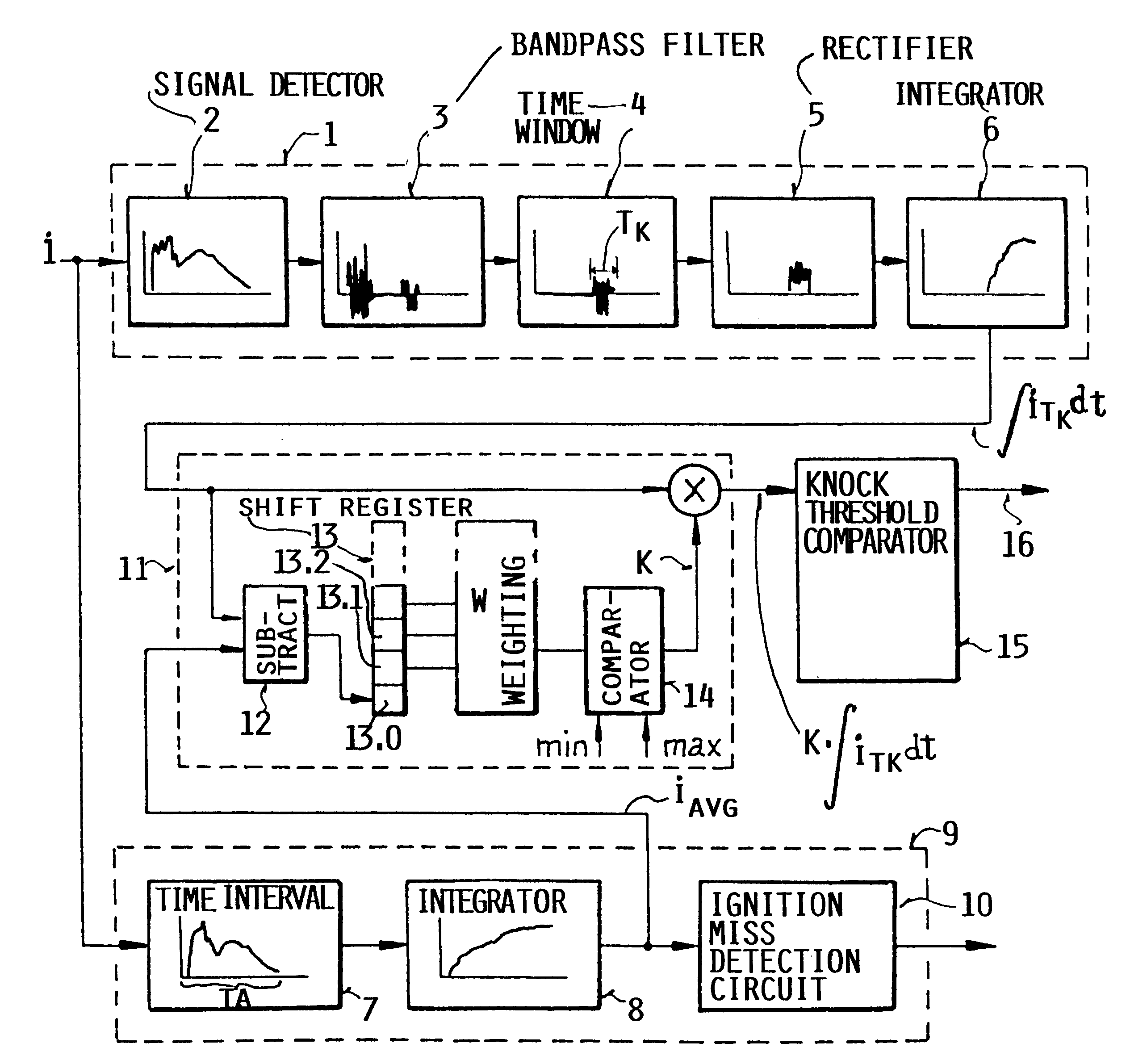
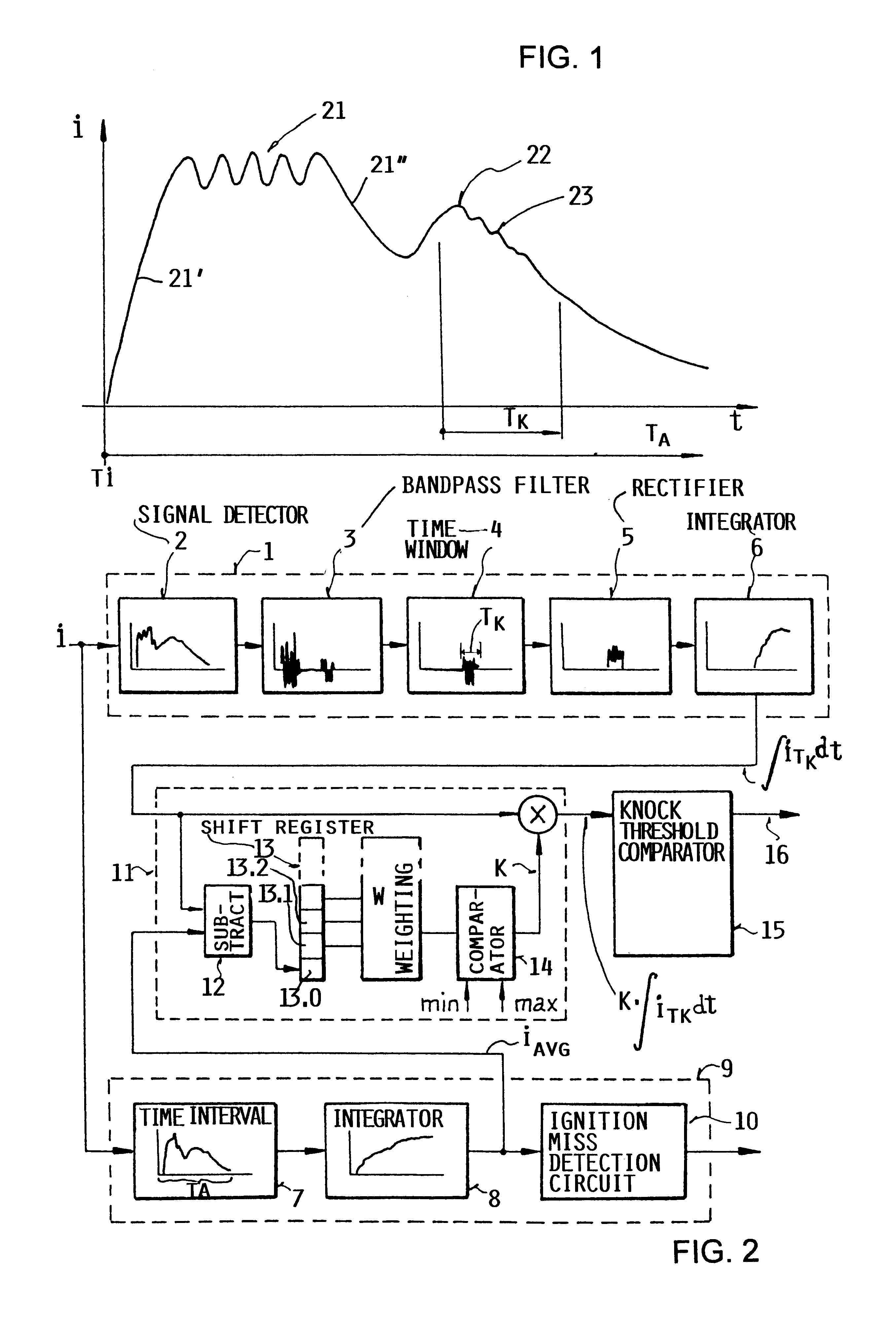
FIG. 1 shows the time progress of the ionic current signal i during a single combustion cycle in a cylinder of an internal combustion engine. It should be understood that the present method and apparatus can be respectively used in connection with any one or more of the cylinders in an engine. After the time of ignition Ti, the flame front expands through the combustion chamber and causes a sharp increase 21' in the ionic current signal i up to the primary signal maximum 21. The signal level at the primary maximum 21 may exhibit oscillations due to turbulence and the like as the flame front progresses through the combustion chamber.

Thereafter, the signal level of the ionic current signal i drops off slightly at 21", and then the signal level again increases up to a secondary local maximum 22 at the point of maximum pressure or compression during the combustion cycle. In the case of combustion without knocking, the amplitude or signal level of the ionic current signal i will smoothly...


PUM

PropertyMeasurementUnit
frequencyaaaaaaaaaa
ionic currentaaaaaaaaaa
timeaaaaaaaaaa

Abstract

A method and an apparatus for detecting knocking combustion in an internal combustion engine, by evaluating the ionic current signal sensed in the combustion chamber, is especially adapted to correct or compensate the ionic current signal for longterm variations arising therein, for example due to variations in the composition of the fuel as a result of contamination with metallic components or the like. Thereby, erroneous knock recognition is prevented. To achieve this, a frequency-filtered time-sampled knocking component integral of the ionic current signal generated in the present combustion cycle is multiplied by a correction value determined from at least one integral value of the ionic current signal generated during at least one prior combustion cycle. The correction value is preferably a time-weighted combination of plural difference values that are respectively determined by subtracting an average integrated value of the ionic current signal from the knocking component integral of the ionic current signal in plural prior combustion cycles, and that are stored in successive positions of a shift register. If the final corrected knocking component integral falls outside of an allowable range, a knock recognition signal is released.

Description

The invention relates to a method and an apparatus for detecting knocking during combustion in an internal combustion engine by evaluating an ionic current signal and electronically adjusting the ignition timing.BACKGROUND INFORMATIONIn the normal combustion of a fuel-air mixture in an internal combustion engine, the fuel-air mixture is ignited by an ignition spark and then burns in a controlled and progressive manner as the flame front advances through the compressed fuel-air mixture in the cylinder chamber. However, an undesired auto-ignition and uncontrolled explosion of the as-yet un-burned fuel-air mixture, commonly known as "knocking", "pinging", or "detonation", can also occur. Such knocking is generally to be avoided because it causes intense pressure waves oscillating in the cylinder, which cause a vibration of the engine components and a resultant audible knocking noise. Ultimately, the intense knocking forces can damage or destroy the engine. Nonetheless, under at least s...

Claims


Application Information

Patent Timeline
Patent Type & Authority Patents(United States)
IPC IPC(8): F02P17/12G01L23/00G01L23/22
CPCF02P17/12G01L23/225
Inventor WILSTERMANN, HARTUNGHOHNER, PETERBERTELSHOFER, PETERSCHENK, JUERGEN
Owner DAIMLER AG
Why Eureka
Try Eureka