Electrophoretic display and method for driving panel thereof

Active Publication Date: 2014-07-24
E INK HLDG INC
View PDF8 Cites 63 Cited by
  • Summary
  • Abstract
  • Description
  • Claims
  • Application Information

AI Technical Summary

Benefits of technology

[0009]Accordingly, the invention is directed to a driving method of an electrophoreti

Problems solved by technology

However, the conventional panel driving technique generally has a cross talk phenomenon caused by a capacitive coupling effect.
Therefo

Method used


Image

  • Electrophoretic display and method for driving panel thereof
  • Electrophoretic display and method for driving panel thereof
  • Electrophoretic display and method for driving panel thereof

Examples


Embodiment Construction

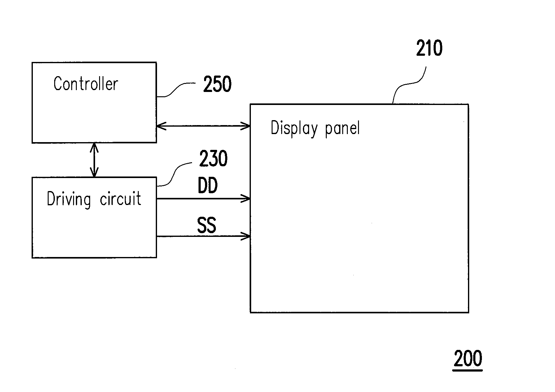
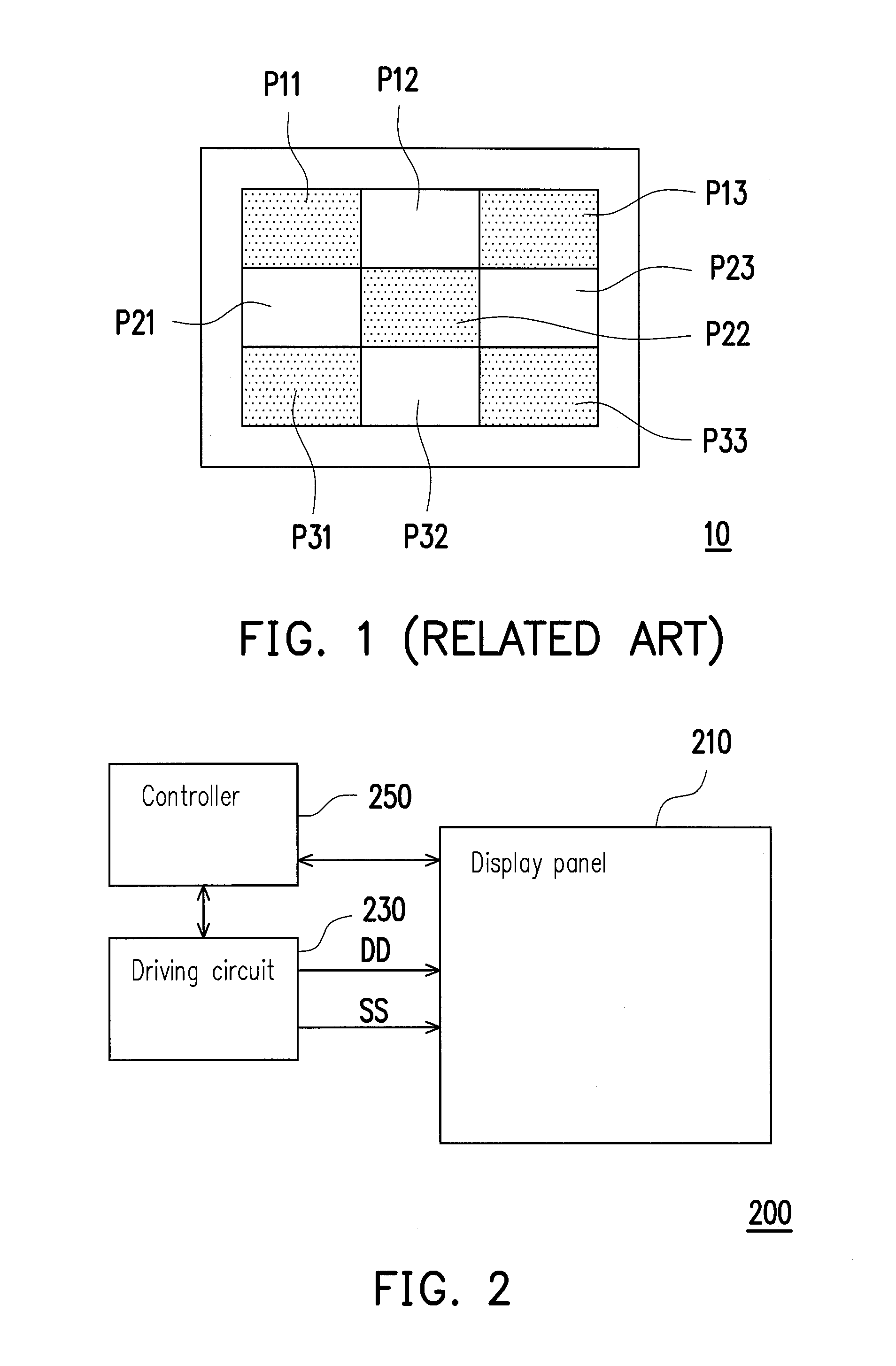
[0023]Referring to FIG. 2, FIG. 2 is a schematic diagram of an electrophoretic display 200 according to an embodiment of the invention. In FIG. 2, the electrophoretic display 200 includes a display panel 210, a driving circuit 230 and a controller 250. The controller 250 is coupled to the driving circuit 230, and the driving circuit 230 is coupled to the display panel 210. The driving circuit 230 is controlled by control signals provided by the controller 250 to respectively provide a plurality of data driving signals DD and scan signals SS to column data lines and row scan lines on the display panel 210, so as to drive the display panel 210 to display required images.

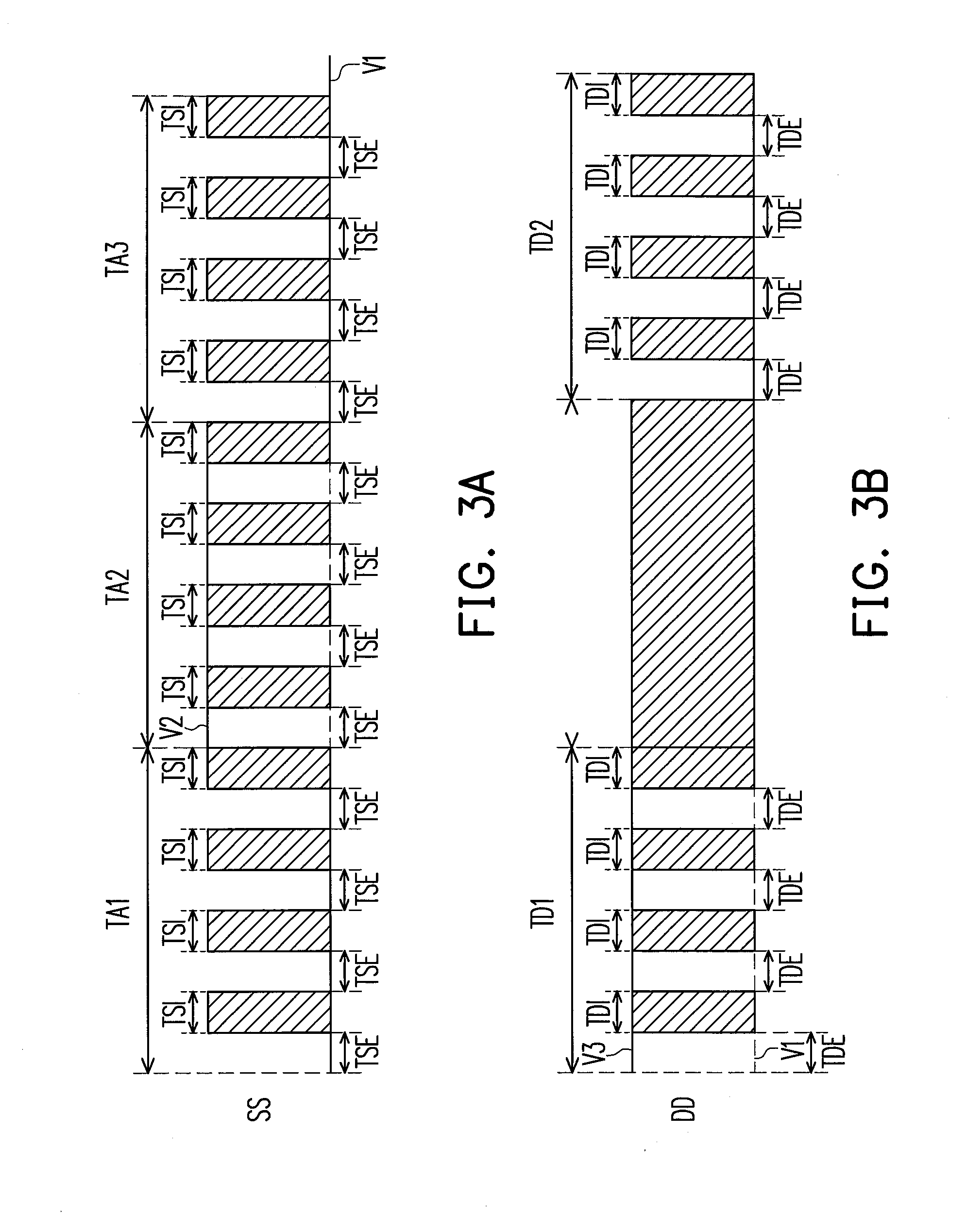
[0024]In the present embodiment, each of the scan signals SS provided by the driving circuit 230 includes a plurality of scan enable periods, and each of the scan enable periods includes a plurality of scan interval periods. Referring to FIG. 2 and a waveform diagram of the scan signal SS of FIG. 3A. The scan signal SS...


PUM


Abstract

An electrophoretic display and method for driving panel using the same are provided. The electrophoretic display includes a display panel and a driving circuit. The display panel includes a plurality of column data lines and a plurality of row scan lines. The driving circuit provides a plurality of data driving signals to the column data lines, and provides a plurality of scan signals to row scan lines. Each of the scan signals has a plurality of scan enable periods, and each of the scan enable periods includes a plurality of scan interval periods. Each of the scan signals is floating or grounding during the scan interval periods. Each of the data driving signals includes a plurality of data driving periods, and each of the data driving periods includes a plurality of driving interval period. Each of the data driving signals is floating or grounding during the driving interval period.

Description

CROSS-REFERENCE TO RELATED APPLICATION[0001]This application claims the priority benefit of Taiwan application serial no. 102102686, filed on Jan. 24, 2013. The entirety of the above-mentioned patent application is hereby incorporated by reference herein and made a part of this specification.BACKGROUND[0002]1. Technical Field[0003]The invention relates to a planar display technique. Particularly, the invention relates to an electrophoretic display and a method for driving a panel thereof.[0004]2. Related Art[0005]Generally, an electrophoretic display applies an electrophoretic display technique to achieve an image display effect. Taking a color e-book as an example, each pixel therein is mainly composed of a red electrophoresis solution, a green electrophoresis solution and a blue electrophoresis solution doped with white charged particles and formed in different micro-cups, and a voltage is applied to drive the white charged particles to move, such that each pixel can display a col...

Claims


Application Information

Patent Timeline
IPC IPC(8): G09G3/34
CPCG09G3/344
Inventor WU, YAN-LIANGHUNG, CHI-MAOSUN, WEI-MINTIEN, PEI-LINHSU, CHIH-YUANHSIEH, YAO-JENCHENG, HSIAO-LUNG
Owner E INK HLDG INC
Why Eureka
Try Eureka