Drive device for the road wheels of a vehicle

a technology for driving devices and road wheels, which is applied in the direction of gearing details, gearing, transportation and packaging, etc., can solve the problems of inability to expand in the axial direction, and achieve the effect of increasing the installation space requirement and increasing the axial for

Inactive Publication Date: 2014-07-24
ZF FRIEDRICHSHAFEN AG
View PDF7 Cites 0 Cited by
  • Summary
  • Abstract
  • Description
  • Claims
  • Application Information

AI Technical Summary

Benefits of technology

[0006]Therefore, it is an object of the invention to provide a drive device of the type mentioned above that is constructed in a simple manner and that allows the increased axial forces generated by the driving wheels to be supported without an increased installation space requirement.

Problems solved by technology

However, enlargement in the axial direction is impossible because the installation space is limited by the rims of the road wheels, by the tire clearance for the latter and by the differential bearings.

Method used


Image

  • Drive device for the road wheels of a vehicle
  • Drive device for the road wheels of a vehicle

Examples


Embodiment Construction

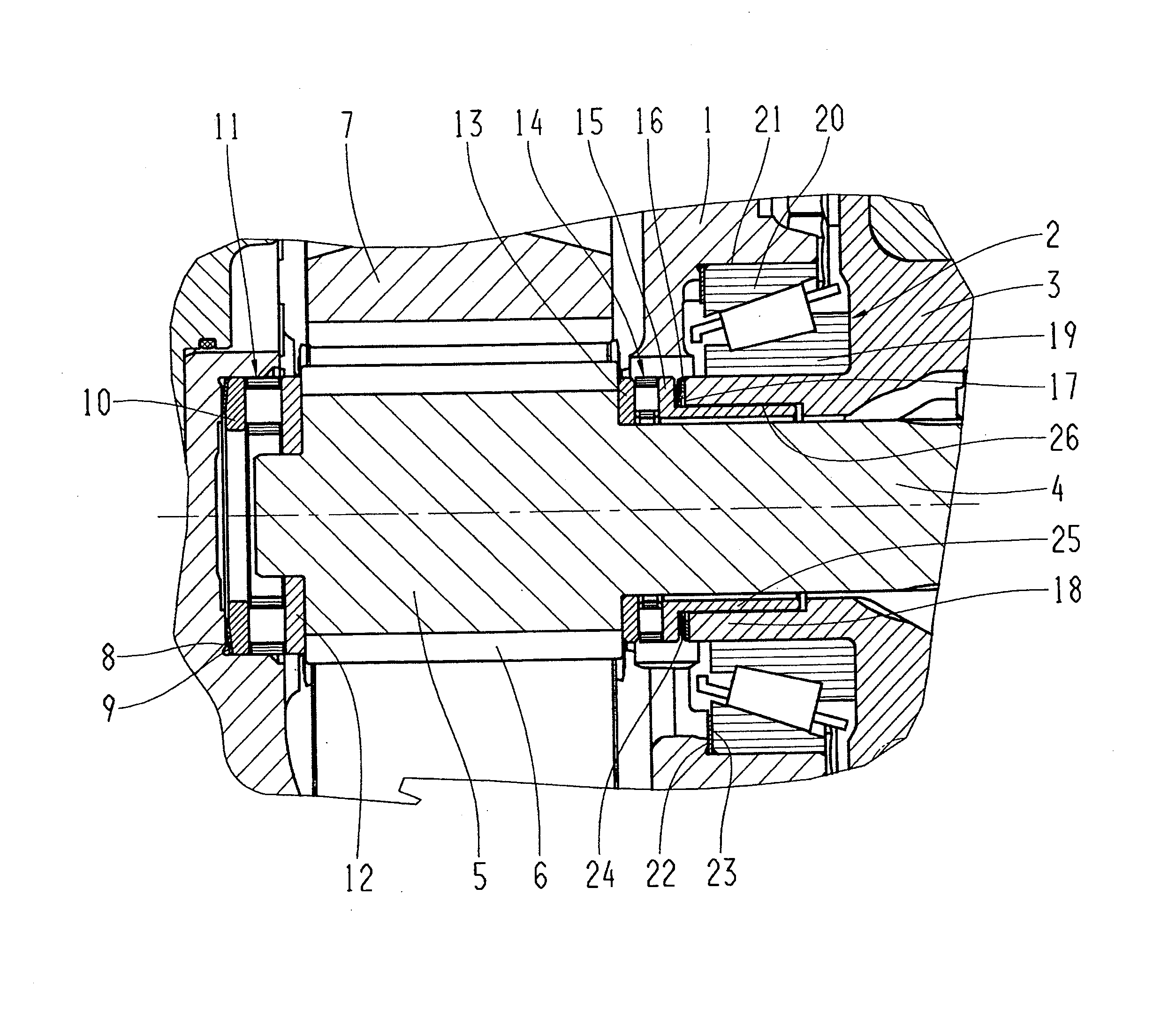
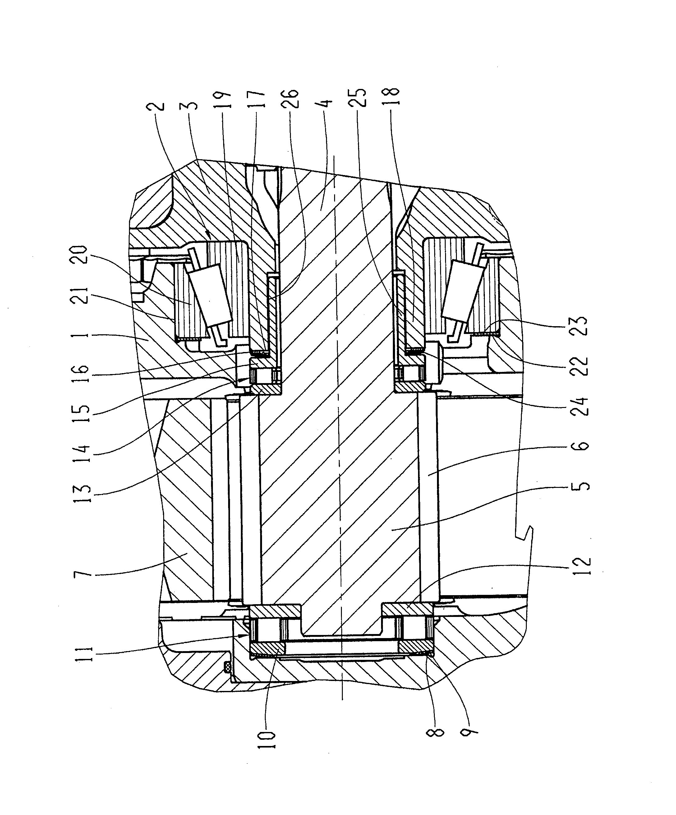
[0021]As seen in the FIGURE, a rotatably drivable differential housing 3 of an axle differential gear unit, not shown, is rotatably mounted in a housing 1 by two differential bearings 2, one of which is shown.

[0022]Two driveshafts 4 are rotatably drivable in a diametrically opposed manner by the axle differential gear unit. The section illustrated in the FIGURE shows the area of one of these driveshafts 4.

[0023]At its end remote of the axle differential gear unit, the driveshaft 4 is formed integral with a driving gear wheel 5 having a helical toothing 6. The driving gear wheel 5 is in meshing engagement with a driven wheel 7 such that a road wheel (not shown) of a vehicle can be driven in rotation.

[0024]The housing 1 encloses the end of the driveshaft 4 having the driving gear wheel 5. Supported on the base of a coaxial recess 8 of the housing 1 is a plate spring 9, which pre-loads the driving gear wheel 5 and the driveshaft 4 in direction of the differential housing 3 via a runnin...


PUM


Abstract

A drive device for road wheels of a vehicle includes: a stationary housing; a rotatably drivable differential housing with an axle differential gear unit, the differential housing being rotatably mounted in the stationary housing by differential bearings; at least one driveshaft rotatably drivable by the rotatably drivable differential housing; at least one driving gear wheel associated with and arranged on the at least one driveshaft, so as to be fixed with respect to rotation relative to the at least one driveshaft; and at least one driven gear wheel, the at least one driving gear wheel meshingly engaging, by oppositely directed helical teeth, with the at least one driven gear wheel to drive the road wheels of the vehicle and generate axial forces directed toward the center of the axle differential gear unit, and having at least one thrust bearing arrangement configured to support the axial forces.

Description

BACKGROUND OF THE INVENTION[0001]1. Field of the Invention[0002]The invention is directed to a drive device for the road wheels of a vehicle with a stationary housing in which a rotatably drivable differential housing with an axle differential gear unit is rotatably mounted by differential bearings, typically two driveshafts being rotatably drivable by the differential housing, a driving gear wheel being arranged on the two driveshafts in each instance so as to be fixed with respect to rotation relative to the latter. The driving gear wheels meshingly engage by oppositely directed helical teeth with driven gear wheels for driving road wheels of the vehicle and generate axial forces directed toward the center of the axle differential gear unit, with thrust bearing arrangements for supporting these axial forces, these thrust bearing arrangements being in turn supported at a structural component part of the drive device.[0003]2. Description of the Related Art[0004]In a drive device of ...

Claims


Application Information

Patent Timeline
Patent Type & Authority Applications(United States)
IPC IPC(8): F16H48/38
CPCF16H48/38F16H57/0006F16H2048/426B60K17/046F16H48/42F16H2048/423F16H57/031
Inventor SIGL, HORSTLENZ, PAULHASELBERGER, PETERNEUMULLER, RUDOLFALESCH, KLAUSENDERL, ALEXANDER
Owner ZF FRIEDRICHSHAFEN AG
Why Eureka
Try Eureka