Linear actuator and rehabilitation device incorporating such an actuator

a technology of linear actuators and actuators, applied in the field of linear actuators, can solve the problems and achieve the effect of increasing the transverse reducing the overall size of the actuator

Active Publication Date: 2015-03-24
FOND INST ITAL DI TECH
View PDF8 Cites 6 Cited by
  • Summary
  • Abstract
  • Description
  • Claims
  • Application Information

AI Technical Summary

Benefits of technology

[0006]According to a preferred embodiment of the invention, the axis of rotation of the driving pulley is oriented parallel to the axial direction, i.e. to the direction of the sliding movement of the output member, so as to reduce the overall size of the actuator in the transverse direction, i.e. in a direction perpendicular to the aforesaid axial direction. In this case, the motion conversion mechanism further includes a pair of guide pulleys each associated to a respective flexible cable length to deviate the direction of this latter from transverse to axial. Alternatively, the axis of rotation of the driving pulley may be oriented perpendicular to the axial direction. This allows to avoid the use of the two guide pulleys, but results in an increase in the transverse overall size of the actuator.

Problems solved by technology

This allows to avoid the use of the two guide pulleys, but results in an increase in the transverse overall size of the actuator.

Method used


Image

  • Linear actuator and rehabilitation device incorporating such an actuator
  • Linear actuator and rehabilitation device incorporating such an actuator
  • Linear actuator and rehabilitation device incorporating such an actuator

Examples


Embodiment Construction

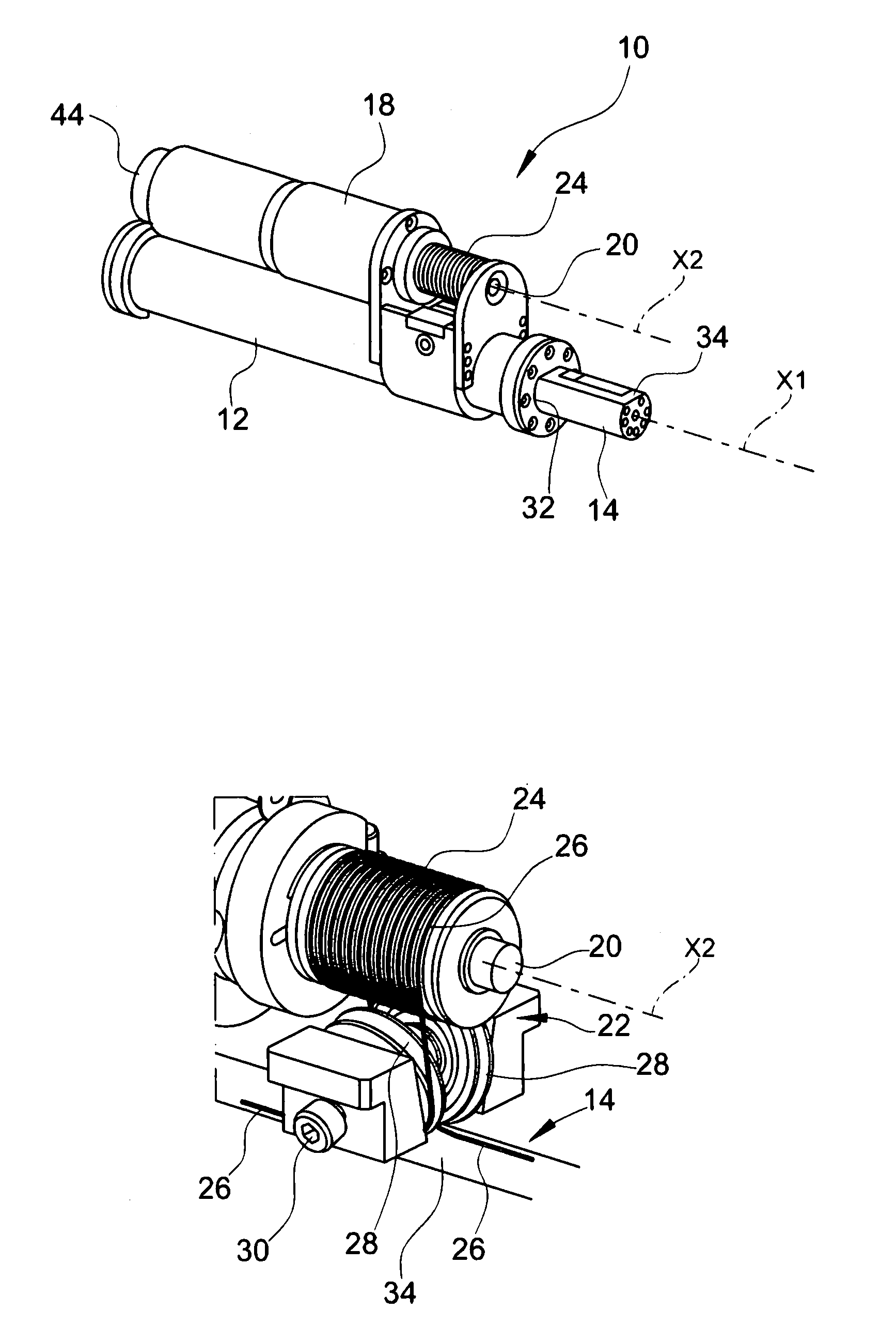
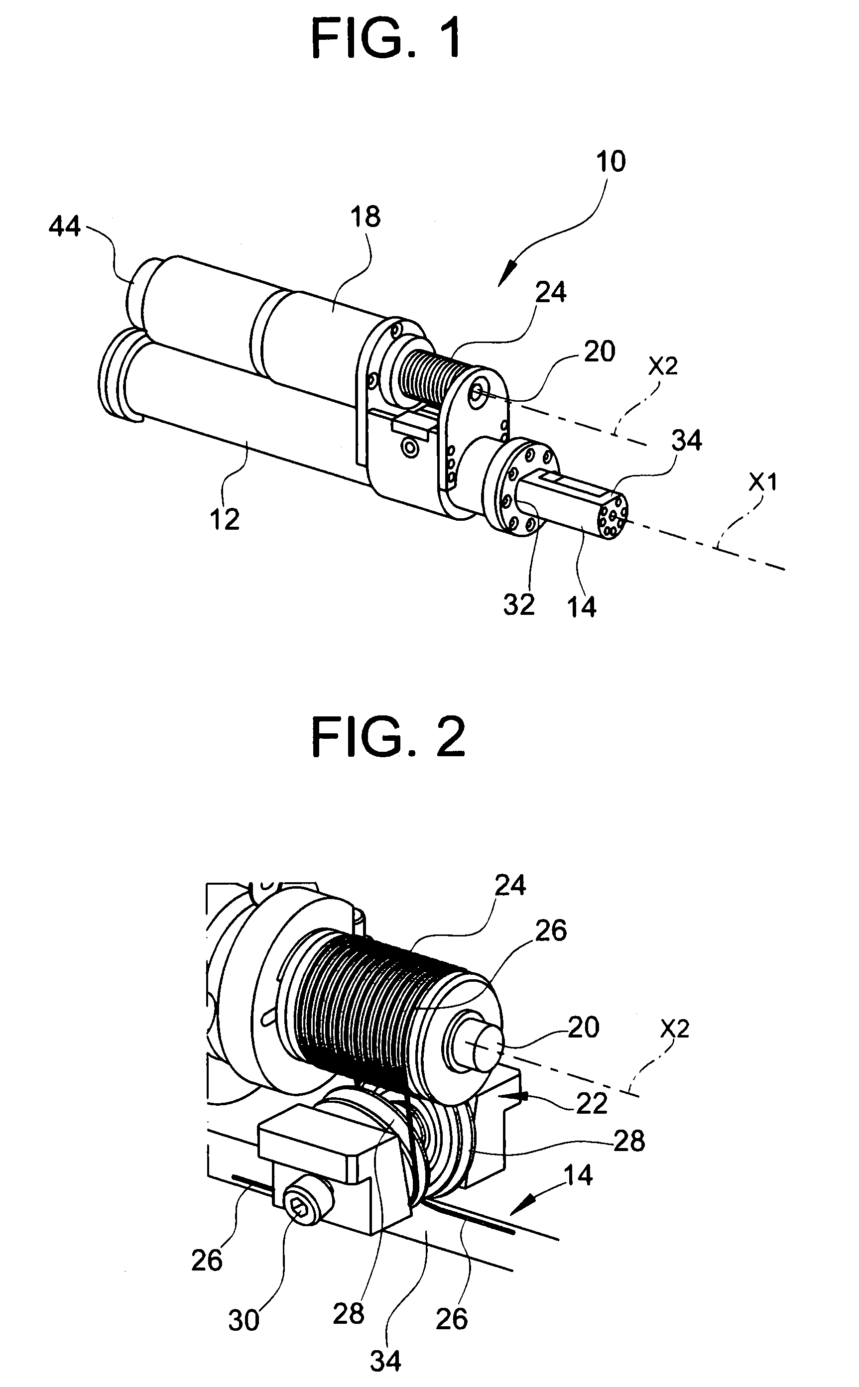
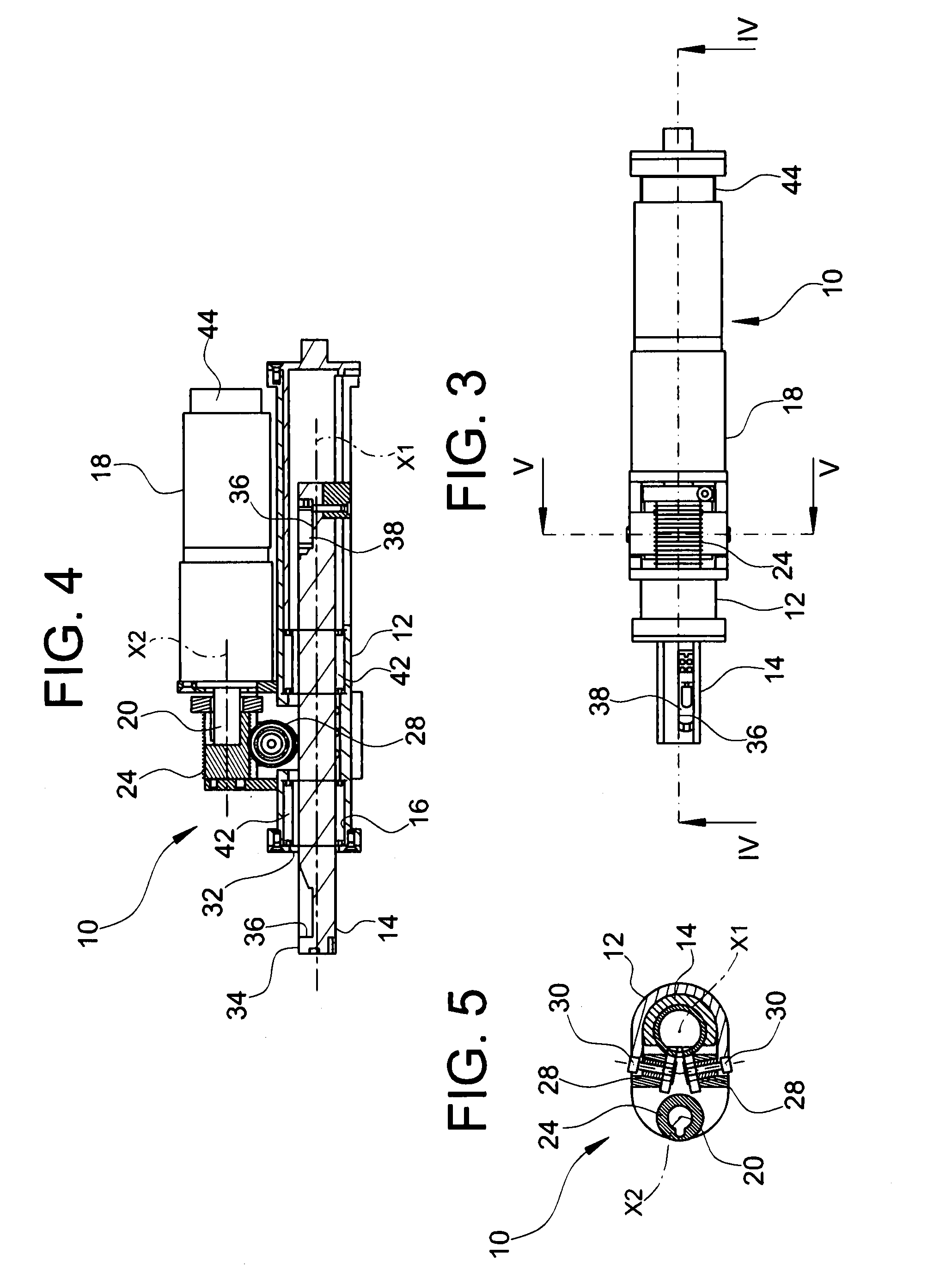
[0018]With reference first to FIGS. 1 to 6, a linear actuator according to a preferred embodiment of the present invention is generally indicated 10 and comprises:[0019]a hollow body 12, preferably having a generally cylindrical shape;[0020]an output member 14 in the shape of a rod which is received in a cylindrical cavity 16 of the body 12 so as to be able to slide in the direction of the axis of that cavity (indicated X1), which direction will be hereinafter referred to as axial direction;[0021]an electric motor 18, preferably coupled to a reduction gear, which motor is mounted on the body 12 and has a motor shaft 20 arranged with its own axis (indicated X2) parallel to the axis X1 of the cavity 16; and[0022]a motion conversion mechanism 22 interposed between the motor shaft 20 of the electric motor 18 and the rod 14 to convert the rotary motion, in either direction, of the first one about its own axis X2 in a translational motion, in either direction, of the second one along its ...


PUM


Abstract

An actuator (10) includes a body (12), an output member (14) slidably received in the body (12) along— a first axis (X1), an electric motor (18) arranged to set into rotation a motor shaft (20) about a, second axis (X2) and a motion conversion mechanism (22) for converting the rotary motion produced by the electric motor (18) about the second axis (X2) into a translational motion of the output member (14) along the first axis (X1). The motion conversion mechanism (22) includes a driving pulley (24) which is drivingly connected for rotation with the motor shaft (20) and an elongated mechanical transmission member which is wound onto the driving pulley (24) and is fastened at its two opposite ends to the output member (14) to draw this latter in either direction along the first axis (X1) as a result of the rotation of the driving pulley (24) in either direction. The output member (14) is shaped as a rod and is received in a cylindrical cavity (16) of the body (12) so as to project partially therefrom. The elongated mechanical transmission member (2S) is fastened to the output member (14) at axially opposite points of this latter with respect to the driving pulley (24).

Description

[0001]This application is a National Stage Application of PCT / IB2010 / 050310, filed 25 Jan. 2010, which claims benefit of Serial No. TO2009A000042, filed 23 Jan. 2009in Italy and which applications are incorporated herein by reference. To the extent appropriate, a claim of priority is made to each of the above disclosed applications.BACKGROUND OF THE INVENTION[0002]The present invention refers to a linear actuator, and more in particular to an electro-mechanical linear actuator basically comprising a body, an output member slidably received in the body along an axial direction, an electric motor (or gear motor) and a motion conversion mechanism for converting the rotary motion produced by the electric motor into a translational motion of the output member along the aforesaid axial direction, wherein the motion conversion mechanism includes a driving pulley set into rotation by the electric motor and a cable, or similar elongated mechanical transmission member, which is wound onto the...

Claims


Application Information

Patent Timeline
Patent Type & Authority Patents(United States)
IPC IPC(8): A61H1/00A61H1/02F16H19/06
CPCF16H19/0618A61H1/0266A61H2201/5061A61H2201/5064Y10T74/18848
Inventor SAGLIA, JODY A.TSAGARAKIS, NIKOS G.DAI, JIAN S.CALDWELL, DARWIN G.
Owner FOND INST ITAL DI TECH
Why Eureka
Try Eureka