Electrical machine

a technology of electric machines and bearings, applied in the direction of rigid support of bearing units, mechanical energy handling, mechanical apparatus, etc., can solve the problems of relatively steep increase in force in the axial direction, relatively complex design of bearing arrangements, and steep increase in load on bearings

Active Publication Date: 2008-12-16
SEG AUTOMOTIVE GERMANY GMBH
View PDF11 Cites 7 Cited by
  • Summary
  • Abstract
  • Description
  • Claims
  • Application Information

AI Technical Summary

Benefits of technology

[0006]The electrical machine according to the present invention has the advantage that a large range of spring-force characteristics with a relatively flat increase in force is attainable. This means that the spring force and, as a result, the axial force load on the bearing may increase slightly across the range of the intended compression of the spring element. As a result, the service life that can be expected of this bearing is markedly increased.
[0008]According to a further subclaim, it is provided that the hub projection has a basically annular shape with a conical spring-support area that declines in the outward direction. As a result of these features, the spring element bears in a defined manner in the radially inward region, which also makes it possible to leave the effective leverage of the spring force unchanged or nearly unchanged. In addition, a simple tool geometry for manufacturing this surface against which the spring element bears is made possible, thereby also extending the service life of the tool. Due to the fact that the spring element configured as a disc spring essentially has the shape of a frustoconical shell, a high axial force can be achieved, so the rolling elements in the rolling bearing roll in their races under defined conditions. This results in a favorable service life for the rolling bearing.
[0009]According to a further exemplary embodiment, it is provided that a spacer is located in the force-transfer direction between the bearing and the spring element. This spacer, as does the hub projection provided with an outwardly declining conical spring-support surface, enables positioning in the hub without causing a change in the leverage of the axially-acting spring force. The bearing is therefore able to absorb axial vibrations relatively elastically without undergoing excessive changes in force.
[0011]The spacer can be, e.g., an originally separate ring fastened to a spring element, thereby resulting overall in an economical creation of a combination of spring element and spacer.

Problems solved by technology

The design of this bearing arrangement is relatively complex, since a number of components is required to exert an axial load on the roller bearing.
Moreover, with a bearing arrangement of this type, only a relatively steep increase in force in the axial direction can be achieved.
Due to longitudinal vibrations of the rotor, then, a relatively steep increase in spring force results and the load on the bearing therefore increases steeply.
A steep increase in the spring load and the resultant high overall axial force load on the bearing is disadvantageous, since this could result in an overload, which would greatly shorten the service life of the bearing.

Method used


Image

  • Electrical machine
  • Electrical machine
  • Electrical machine

Examples


Embodiment Construction

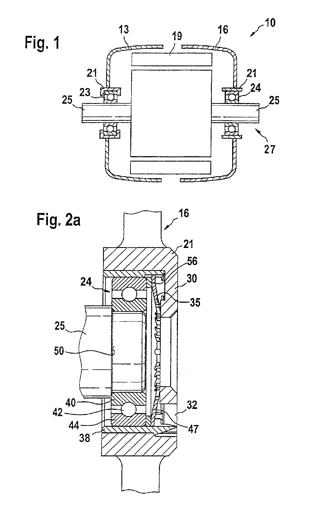
[0020]FIG. 1 shows, in a highly schematic view, a cross section through an electrical machine 10. Electrical machine 10 has, among other things, two housing parts 13 and 16, that accommodate, among other things, a stator 19. Housing parts 13 and 16 each have a hub 21 that serves to support shaft 25 of a rotor 27 via a bearing 23 and a bearing 24.

[0021]Left bearing 23 shown in FIG. 1 is a “fixed bearing”, and bearing 24 shown in FIG. 1 is a “movable bearing”. Movable bearing 24 and its configuration and position in hub 21 will be described in greater detail in conjunction with FIG. 2.

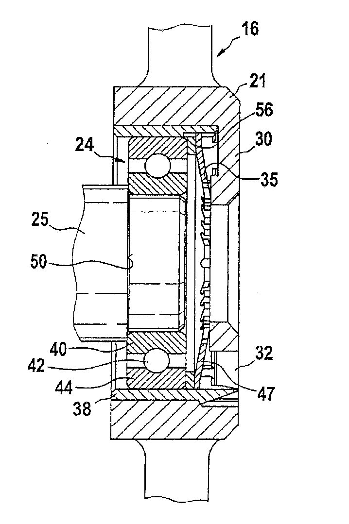
[0022]FIG. 2a shows, in a less schematic illustration, the arrangement of right bearing 24, movable bearing in hub 21, and bearing housing part 16. Housing part 16, often also referred to as an end plate, has hub 21 in its center, the hub extending axially in the shape of a cylindrical ring. A “hub projection”30 adjoins hub 21, the hub projection extending radially inwardly. Hub projection 30 is located ...


PUM


Abstract

An electrical machine has a rotatably supported rotor, at least one bearing for supporting the rotor in a hub, a spring element having an axially-acting spring force which acts on the bearing and also bearing against the hub with the spring force, the spring element being configured as a disc spring functionable back and forth across a flat position of the spring element, the spring element, in an outer region, bearing against an outer ring of the bearing and, in an inner region, bearing against a hub projection, the hub projection being substantially annular in shape and having a conical spring-support surface that declines outwardly in a radial direction.

Description

CROSS-REFERENCE TO A RELATED APPLICATION[0001]The invention described and claimed hereinbelow is also described in German Patent Application DE 103 24 621.5 filed on May 28, 2003. This German Patent Application, provides the basis for a claim of priority of invention under 35 U.S.C. 119(a)-(d).BACKGROUND OF THE INVENTION[0002]The present invention relates to an electrical machine, in particular a generator for motor vehicles, according to the general class of the independent claim.[0003]An electrical machine designed as an alternator is made known in DE 198 04 328 A1, in the case of which the generator shaft is supported by a movable bearing in the hub of a housing part. A spring element inserted in the hub exerts a load on the outer ring of the movable bearing with an axial force to achieve a defined rolling motion of the rolling elements in the movable bearing and thereby attain a longer service life of the movable bearing. The design of this bearing arrangement is relatively comp...

Claims


Application Information

Patent Timeline
Patent Type & Authority Patents(United States)
IPC IPC(8): F16C25/06F16C25/08F16F1/32H02K5/173H02K5/24H02K7/08
CPCF16C25/08F16F1/324H02K5/1732H02K7/083H02K5/24H02K2205/03H02K2213/09F16C35/077F16C19/06F16C25/083F16C2380/26
Inventor HOEFS, ROLAND
Owner SEG AUTOMOTIVE GERMANY GMBH
Why Eureka
Try Eureka