
Torque Sharing Drive And Torque Sharing Process

Active Publication Date: 2014-07-31
GUSTOMSC RESOURCES BV
View PDF10 Cites 31 Cited by
  • Summary
  • Abstract
  • Description
  • Claims
  • Application Information

AI Technical Summary

Benefits of technology

The present invention is a torque sharing drive that can accommodate variations in the dimensions of the parts used to mount the drive. It also allows for load sharing by allowing the drive pinion to float and seek equal loading with the gears. The gear meshes are designed to provide sufficient space for the variations in the system. The invention also includes a gear train that can handle imperfections and inaccuracies.

Problems solved by technology

Imperfections may occur in the teeth of the rack and the teeth of the pinion which drives the rack.
Imperfections may occur in the assembly of the torque sharing drive.
Imperfections may occur in the alignment and mounting of the torque sharing drive.
Additionally, there may also be inaccuracies in the torque sharing drive assembly mounting and spacing between components thereof.
Additionally, backlash is the amount of clearance between the rack and pinion tooth flanks.

Method used


Image

  • Torque Sharing Drive And Torque Sharing Process
  • Torque Sharing Drive And Torque Sharing Process
  • Torque Sharing Drive And Torque Sharing Process

Examples


Embodiment Construction

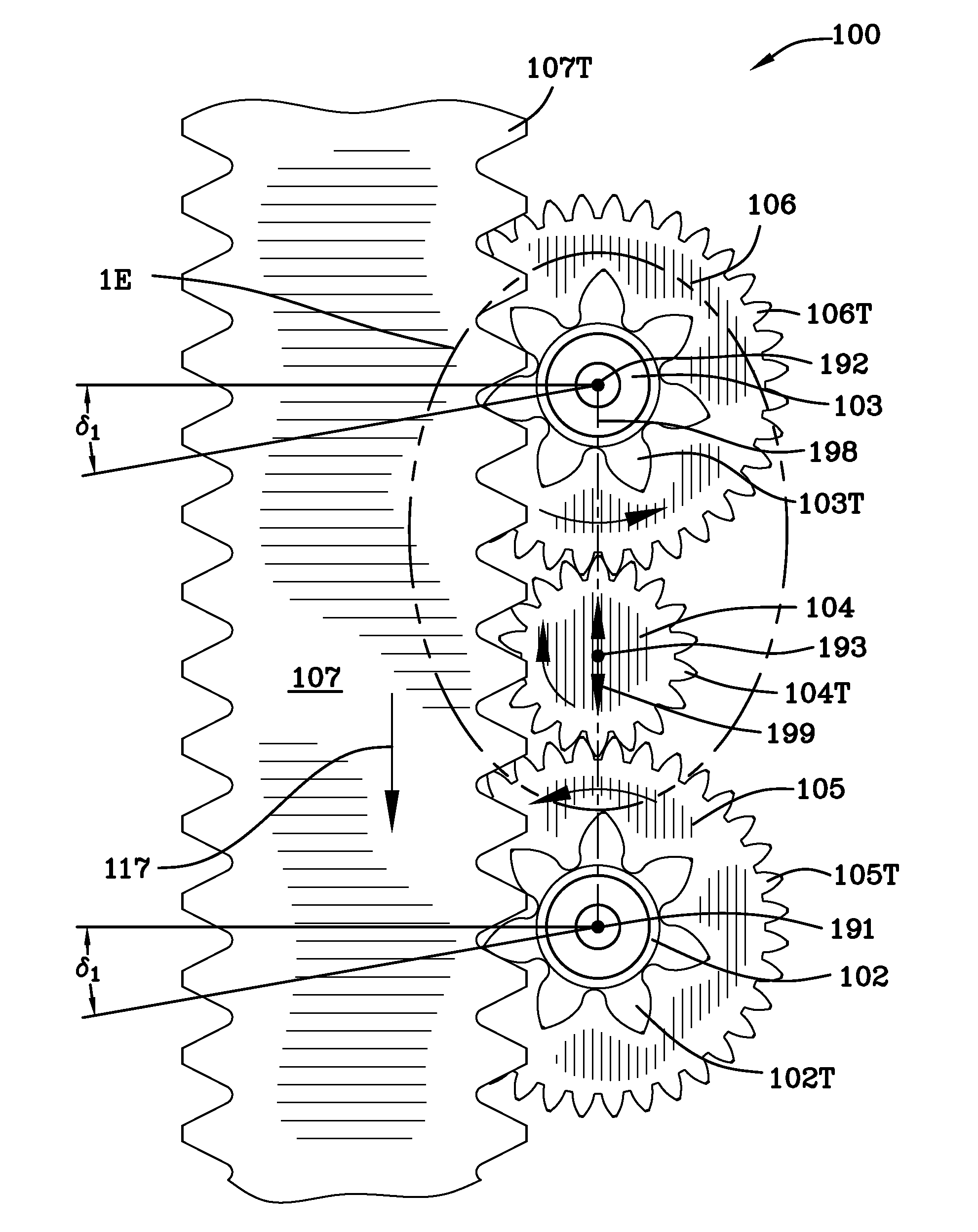
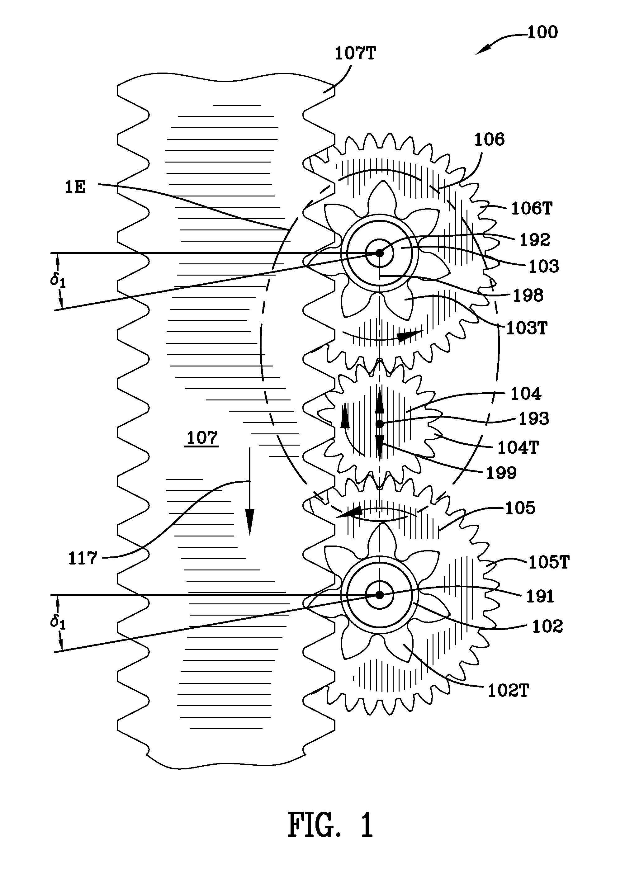
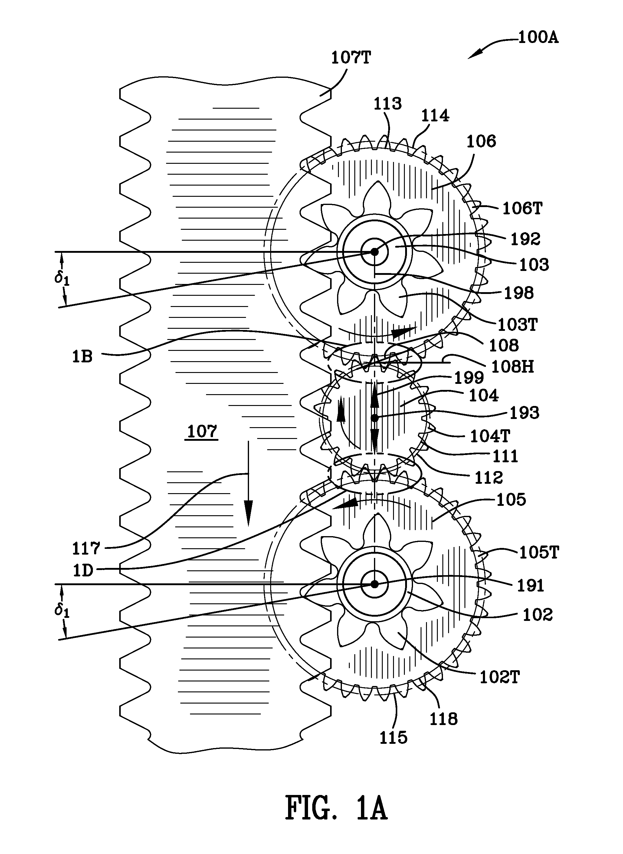
[0075]FIG. 1 is a schematic view 100 of the torque sharing drive illustrating the rack 107 and pinion drive 102, 103, and, the movable driving pinion 104 residing equidistantly intermediate the first gear 105 and the second gear 106. Driving pinion 104 is movable, radially, bidirectionally, in the vertical direction when viewing FIGS. 1 and 1A as indicated by arrow 199. Driving pinion 104 includes a shaft 104A having a crowned external spline 104S which engages a torque driver 201 having an internal driving spline 201S. The torque driver 201 may be powered by various devices, for instance, the torque driver 201 may be powered by a planetary gear set. See FIGS. 2 and 8A which illustrate the torque driver 201 and driving spline 201S.

[0076]Driving pinion 104 does not have a fixed center and it is movable, radially, in one direction along line 198 as illustrated in FIGS. 1, 1A, 1B, 1C, and 1D. For instance, driving pinion 104 is movable, radially, vertically either upwardly or downwardl...


PUM


Abstract

A torque sharing drive and process for sharing torque accommodates tooth inaccuracies on the rack and outer pinions. A driving pinion mates with first and second gears. The driving pinion is radially, bidirectionally, movable in response to gear separation forces only along the line between the centers of the driving pinion, the first gear and the second gear. First and second outer pinions are rotatable with the first and second gears, and as the driving pinion moves radially toward the first or second gear in response to gear separation forces, the first or second gear is angularly and rotationally advanced with respect to the other gear accommodating inaccuracies in the teeth of the rack and outer pinions. Alternatively, when gear separation forces are balanced, the driving pinion resides approximately equidistantly intermediate the first and second gear and the first and second outer pinions are approximately in phase.

Description

FIELD OF THE INVENTION[0001]This invention is in the field of torque sharing drives.BACKGROUND OF THE INVENTION[0002]Oil rig platforms and the like are well known in the art. These platforms are commonly used during construction of the oil rig and to support workers and equipment at desired elevations. Platforms are necessarily moved upward and downward and these platforms are known as elevating platform assemblies. It is necessary to lift and lower large loads on oil rig platforms and the like. It is necessary to quickly change the elevation of workers and equipment and thus, elevating platform assemblies are advantageous. Accordingly, jacking drives are securely attached to the platform along with a motor to power the jacking drives thus raising and lowering the platform to the desired elevation.[0003]United States Patent Publication No. US 2007 / 0295136 A1 states, in the abstract: “[a]n anti-backlash system comprising a single drive pinion and motor is disclosed. In an exemplary e...

Claims


Application Information

Patent Timeline
IPC IPC(8): F16H1/22
CPCF16H1/22F16H19/04F16H2057/121Y10T74/19079Y10T74/19623Y10T74/19628Y10T74/1967
Inventor MILLER, RICHARD W.
Owner GUSTOMSC RESOURCES BV
Learn More