
Airtight gasket for pneumatic tool

a pneumatic tool and airtight technology, applied in the field of airtight gaskets for pneumatic tools, can solve the problems of air leakage, machining is required, and the manufacturing process is more difficult, and achieve the effect of increasing the airtight

Inactive Publication Date: 2014-07-31
SUNMATCH INDAL
View PDF1 Cites 0 Cited by
  • Summary
  • Abstract
  • Description
  • Claims
  • Application Information

AI Technical Summary

Benefits of technology

The present invention provides an airtight gasket with an extended airtight convex ring that increases airtight efficacy and an airflow regulation portion. The gasket achieves a secured airtight effect between the air intake passage and regulation valve, which can be compressed and deformed to attain desired air tight efficacy. The airtight convex ring further enhances the air tight efficacy to accomplish airtight effect of the pneumatic tool during directing the high pressure air. Compared with the conventional airtight gasket, the invention has an extended airtight convex ring that provides improved compressibility to tightly seal the gap between the structural elements and facilitate assembly of the pneumatic tool.

Problems solved by technology

Air leakage could still take place.
Hence precise machining is required and fabrication is more difficult.
Moreover, the conventional airtight ring forms a plane contact between elements that has a greater contact area and results in deficient compression.
All this makes production cost higher.

Method used


Image

  • Airtight gasket for pneumatic tool
  • Airtight gasket for pneumatic tool
  • Airtight gasket for pneumatic tool

Examples


Embodiment Construction

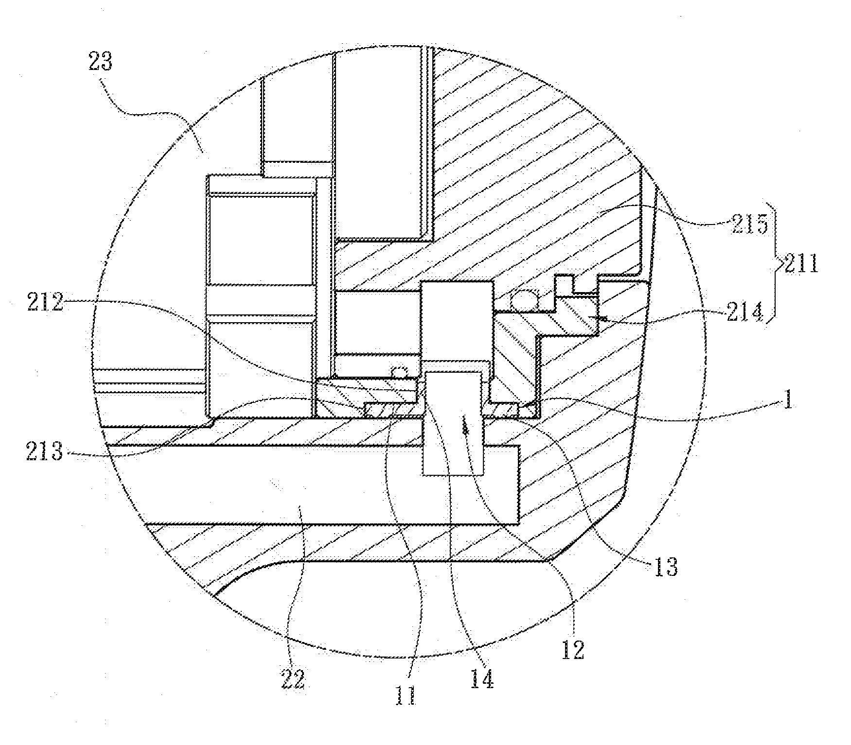
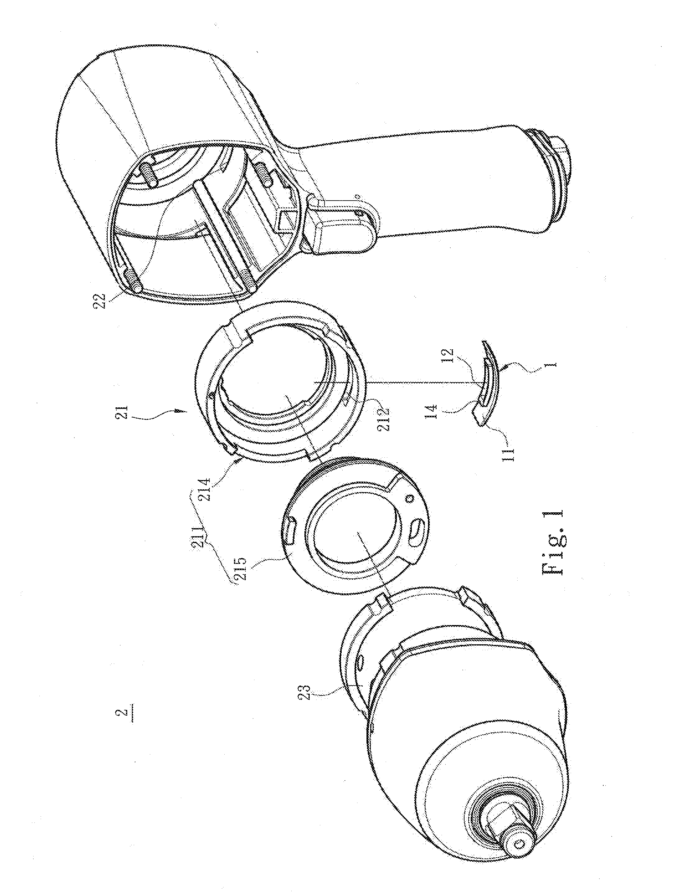
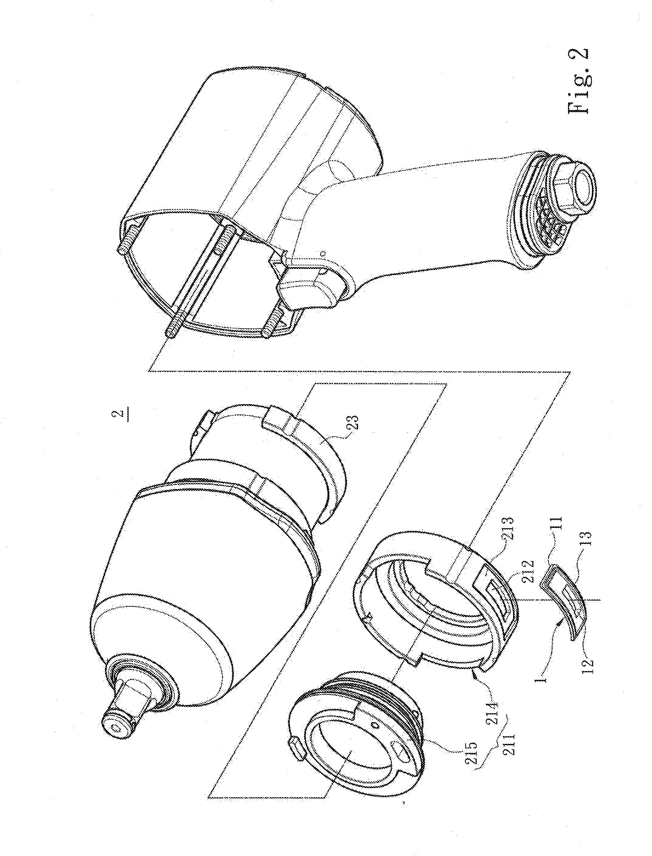
[0017]Please referring to FIGS. 1 and 2, the present invention aims to provide an airtight gasket 1 installed on a pneumatic tool 2. The pneumatic tool 2 employs high pressure air as a driving source to do operation of striking or drilling. The pneumatic tool 2 includes an airflow regulation portion 21, an air intake passage 22 to direct the high pressure air into the airflow regulation portion 21 and a pneumatic motor 23 to receive the high pressure air from the airflow regulation portion 21 to generate spinning. The airflow regulation portion 21 mainly includes a regulation valve 211 corresponding to the air intake passage 22 and containing a flow directing vent 212 opened to the airflow passage 22 and a recess 213 surrounding the flow directing vent 212. The flow directing vent 212 communicates with the air intake passage 22 and airflow regulation valve 211 to direct the high pressure air in the air intake passage 22 to pass through the flow directing vent 212 to enter the regula...


PUM


Abstract

An airtight gasket for a pneumatic tool including an airflow regulation portion, an air intake passage to direct high pressure air into the airflow regulation portion and a pneumatic motor to receive the high pressure air from the airflow regulation portion and generate spinning. The airflow regulation portion includes a regulation valve which contains a flow directing vent corresponding to the air intake passage and a recess surrounding the flow directing vent. The airtight to gasket is clamped between the regulation valve and air intake passage, and includes a base located in the recess, a through-hole located on the base to channel the high pressure air into the flow directing vent, and an airtight convex ring surrounded the through-hole and extended integrally from the base towards to air intake passage.

Description

FIELD OF THE INVENTION[0001]The present invention relates to an airtight gasket for pneumatic tool and particularly to an airtight gasket that has an extended airtight convex ring to enhance airtight efficacy with an air intake passage.BACKGROUND OF THE INVENTION[0002]A conventional pneumatic tool such as one disclosed in R.O.C. patent 1252796 employs high pressure air as a driving source to drive a spindle of a pneumatic motor to spin and a drilling tool coupled on the spindle to perform drilling operation.[0003]Moreover, the general pneumatic tool has a high pressure airflow path, such as that disclosed in R.O.C. patent M262329, that includes an air intake passage formed on a housing to receive the high pressure air which passes through an airflow regulation element to change airflow direction, then the high pressure air enters an air chamber to drive a pneumatic motor to spin. In order to ensure that the high pressure air can flow according to the designed airflow path after ente...

Claims


Application Information

Patent Timeline
Patent Type & Authority Applications(United States)
IPC IPC(8): F16J15/06
CPCF16J15/06B25F5/00Y10T137/7722
Inventor CHEN, LUNG-PAO
Owner SUNMATCH INDAL
Learn More